Continue to Site

Eng-Tips is the largest engineering community on the Internet

Intelligent Work Forums for Engineering Professionals

  • Congratulations SDETERS on being selected by the Eng-Tips community for having the most helpful posts in the forums last week. Way to Go!

Behavior of circular shaft support structure

Status
Not open for further replies.

hemiv

Structural
Dec 7, 2018
78
I’m doing some design work for a circular shaft. It’s basically just secant piles supporting themselves in ring compression. I’ve used DeepEX to do some modeling, but that software assumes fully uniform loading around circular shaft walls. Part of our design criteria is to consider nonuniform loads causing the shaft to bend and “egg.” I’ve done some modeling of the cross-section in RISA, but I thought maybe some of you could provide input as to how much load non-uniformity is considered in these types designs. I know conceptually that as the shaft walls deflect, they will begin to engage passive pressures as needed, thereby making the loads more uniform and stabilizing the walls. The questions in my mind are (a) how much deflection is required to engage passive pressures and (b) will my structure fail at or before this required deflection. A quick search yields a good number of examples of these types of designs being built - DeepEX’s website, for one - so, I know there is precedent for this design.

PS - is this a case where the geotech should be giving me horizontal subgrade modulus in order to analyze the non-uniform loading appropriately? If so, I’ll just have to bug them to that value.
 
Replies continue below

Recommended for you

I have never designed a circular shaft but Ill take a shot - To get an idea of the effect of non - uniformity of load on the shaft you will need to do a 3D FEM Plaxis model or the like. Howeve, If you take a 1m section and just consider your adjacent surcharge and what ever additional design point/UDL loads, won’t that give you a maximum bending moment and shear force. If you design your piles and ring beam for these forces you will be conservative as in reality, as you said, the ring compression will act to reduce the forces that are actually felt? Hence, won’t DEep ex, or any other non FEM program that assumes a uniform loading be sufficient? Maybe, maybe not?

(A) - there doesn’t seem to be agreement with the amount of movement required to mobilise passive resistance on this forum. Have a look at the BS for earth retaining structures.

That should be a good start. This indicates up to 10% could be required for a loose sand.

(B) the factor of safety you use in your design (whether on passive pressure, soil strength or embedment length) should be sufficiently large to ensure that displacements are acceptable under SLS working conditions. The higher the factor of safety the less movement you need. You will also have your displacements from DEep ex, Plaxis , WAllap or what ever you use. If your measured deflection on site is more than this then it is likely that your structural forces are above your design forces. While this may not be a dramatic failure, it does mean that your wall doesnt have sufficient structural capacity.
 
I did exactly that. I took a unit depth section of concrete ring and applied the highest load, which is active pressure plus a particular spot with construction equipment surcharge, and applied that to a ring approximation in RISA. At first I did that as a uniform load, assuming that even though there is an equipment surcharge concentration at one point, that will even out as the structure deflects. This of course just verified my hand calculations. The owner came back and asked me to run a model with a particular loading diagram, wherein the maximum load scenario is applied at varying percentages around the circumference. When I do this, the deflections get really big, at the very least 3 times what would be needed for passive engagement, based on a (probably conservative) criterion of 0.05H wall movement.

I look at all of this and think that maybe the owner is asking for a loading scenario that is just not a possible. Nonuniform loads lead to oblong deflections, which lead to passive pressures when the deflections get big enough, which lead to normalization of the load. Which, again, leads me to check the bending moments in the wall just prior to the point of passive engagement and base my FOS on that moment. After that point the wall will be sufficiently braced against further deflections, and the moments won't really increase.

Sorry, just sort of talking out loud here.

DeepEX shouldn't give any displacement for a circular shaft uniformly loaded. The only deflections would be from compression axial load, which would be inward deflections. Outward deflections only come from non-uniform loading. I suppose I will clarify and say that I'm not look at passive pressures in order to balance an overturning moment, I'm looking at them for stability of the circular shaft cross section.
 
hemiv - Any self-supporting circular structure in compression is inherently unstable, especially so with unbalanced loads.
Don't try to predict how much deflection is acceptable... then intentionally allow defection up to that value.

Instead, take steps to prevent any significant deflection for occurring.

You mention seeing examples of similar designs on the DeepEX website. Note this example, where "two concrete ring beams were provided to account for unbalanced loads and minimize risks in case construction tolerances were not met."

As mentioned in that example, installation tolerances are very exacting. Only in recent years have qualified contractors using modern equipment made self-supporting circular excavation wall a viable option. Specification for constrution and adequate on-site verification are just as important as design. Here is a paper on what is practical today: Secant Pile Shoring - Developments in Design & Construction

[idea]
 
SRE, my design does the same thing. We’re providing rings near the top and at a critical location farther down.
 
hemiv - Put the ring beams as low as possible, for two reasons:

1) Chance of misalignment is greatest at the bottom (most distant from the drilling rig)
Tolerance-600_qkqrkz.png


2) Pressure is the highest. If there are going to be "problems", they will occur at or near the bottom.

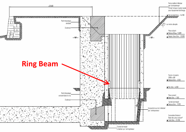
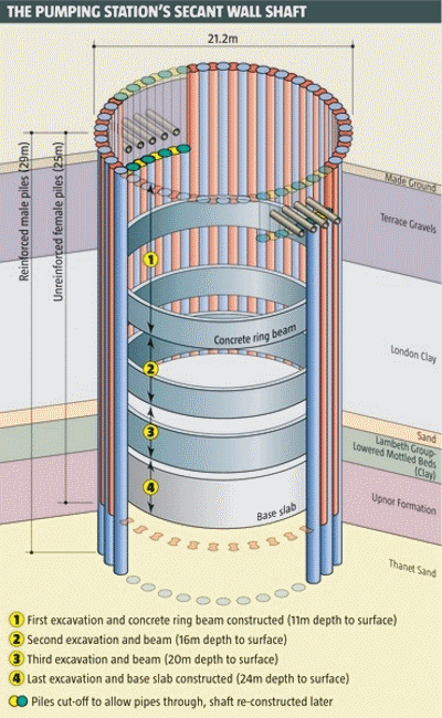
Here are two illustrations of different projects, from the web, that demonstrate putting ring beams low. One is the example I linked to:

Example1-600_emsyco.png


Example2-600_ncnllj.png


Unless your firm has done this type work before, do not be lulled into believing that sophisticated software is going to accurately predict actual behavior. Subsurface work is one of the the few areas in engineering where "art" is as important as "science" in creating a safe, workable design... and the loads are high, real (not statistical probabilities, like wind or seismic), and always present.

[idea]
 
SRE, thanks for the input! We do have one down low based on the point where tolerances void the wall continuity.
 
It can be modelled in a 2-D axisymmetric FEM/FDM model unless your non-uniform surcharge is too high. Numerical model assumes the secant piles are perfectly connected while in reality they are not, they probably never are, but ring beams can hold them together. I have a paper published in 2014 that discussed a case history of a 46m diameter circular shaft, 26m deep excavation in soft marine clay, diaphragm wall panels, 3 ring beams, unbalanced loading, instrumentation vs. predictions (Class A & C), see attached.
 
 https://files.engineering.com/getfile.aspx?folder=6bf89735-07bd-4363-9122-35db153368c8&file=Zhang&Lawrence2014_A_Case_History_of_a_Deep_Excavation_in_a_Big_Circular_Shaft_in_Singapore_Marine_Clay.pdf
Great, thanks! I'll certainly take a look at it!
 
Status
Not open for further replies.

Part and Inventory Search

Sponsor