Continue to Site

Eng-Tips is the largest engineering community on the Internet

Intelligent Work Forums for Engineering Professionals

  • Congratulations KootK on being selected by the Eng-Tips community for having the most helpful posts in the forums last week. Way to Go!

Excavation support 4

Status
Not open for further replies.

hoshang

Civil/Environmental
Jul 18, 2012
479
Hi all,
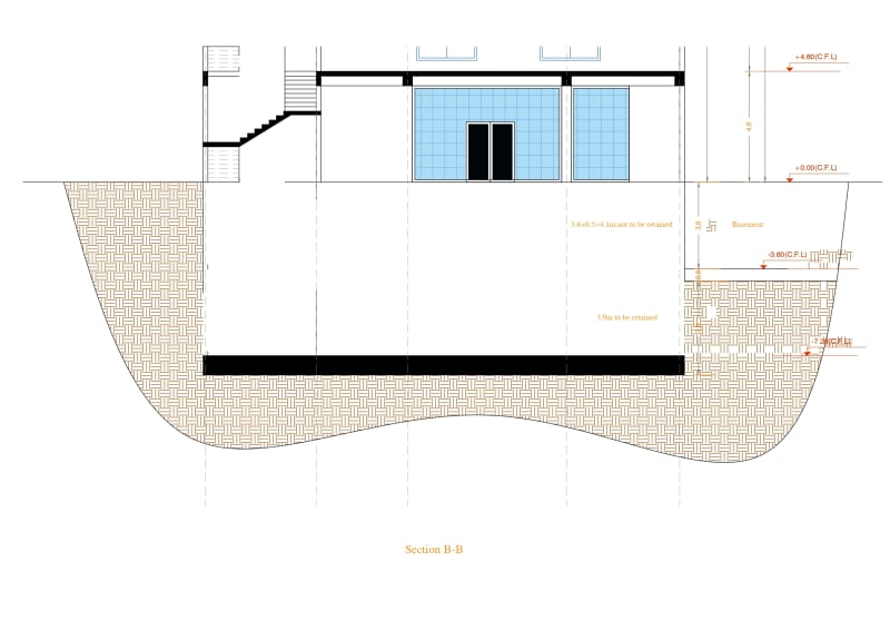
Please find the attached image.
The building has 2 basement floors+ 2 floors (used as shows)+ 4 typical floors (used as flats). The mat foundation is 800mm thick. The basement floors are 3.6m high floor-to-floor each. My first thought is using piles for excavation support. My worry is the piles will interfere with boundary columns. What is the best practice to avoid such a condition?
 
 https://files.engineering.com/getfile.aspx?folder=310f5ae4-43e8-4399-b87a-8d930a4f9339&file=Excavation_support.pdf
Replies continue below

Recommended for you

PEinc said:
Sometimes, long cross braces need some vertical and/or lateral support to reduce their unbraced length.
I think you want to say:
Sometimes, long cross braces need some vertical with/without lateral support to reduce their unbraced length.
In my case I would not prefer some vertical support to reduce long cross braces length since it would interfere with excavation operations. So how one can deal with these long cross braces?
PEinc said:
Install horizontal, corner braces at sheeting corners. This will be easier to build if the new building walls are about 1m off the sheeting walls (the 1m space will need to be backfilled before removing bracing).
The new building walls will be at the sheeting walls (the sheeting wall will be the exterior form for the new building wall).
 
Hi PEinc,
I followed your valuable posts on my and other threads. I appreciate your help. You made it clear the possible solutions. Now, my thought is that the load path of the soil pressure is from the soldier piles to walers, then from walers to cross struts (a straight cross strut is much better than a broken one since it will be subject to compression only from earth pressure with little bending from self-weight). I appreciate your recommendation on corner braces. This may solve a lot. For the perpendicular sides the corner braces are easy to visualize. But the angled (skewed) side is what worries me. Your opinion would be highly appreciated.
 
If you cannot get permission to installed tiedback underpinning, consider a very stiff sheeting layout something like shown here. Remember, the soldier beams take up room and will cause your building to have a smaller footprint. Talk to the project's structural engineer, architect, and a contractor about how close to the existing buildings the soldier beams can be.
[URL unfurl="true"]https://res.cloudinary.com/engineering-com/image/upload/v1705342464/tips/Sheeting_Scheme_hvasyr.pdf[/url]

 
PEinc said:
Pre-load the braces to minimize soldier and brace deflections.
Thanks, PEinc. Can you elaborate more on Pre-loading of the braces? A detailed sketch, or a reference would be helpful. Is it pre-loaded using jacks? How it comes to be pre, rather than post? I mean is it done after installation of the braces or before the installation?
PEinc said:
Possibly four horizontal corner braces
Do mean you've drawn two in this corner. It may need four braces?
 
Pre-loading a brace entails jacking a load, usually 50% to 75% of the brace design load, into the brace after it is installed but before digging deeper than that brace's waler installation elevation. The brace has one or two jacking brackets welded to the brace near the waler so that one or two hydraulic jacks can be set between the bracket(s) and the waler. The resulting gap between the brace and its waler then gets packed with welded plate(s) and the jack is then released and removed.

I was referring to possibly 4 total corner braces, not necessarily 4 in one corner. You need to run the design and see how many braces you need and how big a waler you need to span between all braces.

You need to talk to someone in your area who has done this type of work, both design and construction! You are into this way over your level of experience.

 
Hi PEinc,
What should be done on the lower right corner? Isn't necessary to provide a brace there?
 
The waler along the street side braces the end of the right side waler. The walers need to be designed for combined axial and bending loads. The 4 walers would be connected at the 4 corners.

 
Hi PEinc,
Thanks for your contribution.
On the right side there exists a three floor & basement building. Does the length of the soldier piles on this side be same as those on the other sides?
Another thought came into my mind.
PEinc said:
Pre-loading a brace entails jacking a load, usually 50% to 75% of the brace design load, into the brace after it is installed but before digging deeper than that brace's waler installation elevation.
After pre-loading (pre-compression) a brace, doesn't digging deeper than that brace's waler installation elevation (followed by lagging installation behind the back flange) relieve some pre-loading amount? Should the soldier piles be higher or lower than the bottom of the existing building foundations? If the former, the pre-loading won't put the soil beneath the existing foundation in passive condition. My thought is that the latter will put the soil beneath the existing foundation in passive condition (hence the correct condition for soldier pile installation). Is my approach correct?
 
Usually, you can brace a taller wall against a lower wall. Remember that the lower wall needs to develop enough passive resistance to resist the load from the taller wall. The lower wall's walers and braces would receive a greater load than what is needed to support the lower wall. Generally, the soldier beams for the lower wall need only the length required for the lower wall design - as long as the lower wall can provide sufficient passive support for the taller wall.

When you pre-load a brace or tieback anchor, the pre-load amount should be close to the maximum expected load for the worst case. Therefore, if you dig down about 2m or 2.5m to install the first level of bracing or tieback anchors for a 10m excavation, you would pre-load that level for its required load for the 10m wall.

 
Thanks, PEinc, for your responses.
PEinc said:
Generally, the soldier beams for the lower wall need only the length required for the lower wall design - as long as the lower wall can provide sufficient passive support for the taller wall.
Do you mean for multilevel bracing, the upper bracing will be 3-sided brace? angled (skewed) side, angled (skewed) opposite side, and left side?
PEinc said:
When you pre-load a brace or tieback anchor, the pre-load amount should be close to the maximum expected load for the worst case. Therefore, if you dig down about 2m or 2.5m to install the first level of bracing or tieback anchors for a 10m excavation, you would pre-load that level for its required load for the 10m wall.
But after pre-loading (pre-compression) a brace, doesn't lagging installation behind the back flange relieve some pre-loading amount?
I interpreted your post as a response to a thread as if you were calculating earth pressures rather than net pressures. Do you mean you calculate it as in the attached image?
CE_540_Module_5.1_Sheet_Pile_cantilevered_9-4_screenshot_ub3yc5.png
 
I don't know what you mean in your first question.
When lagging is installed, there usually is no excavation behind the back flange of the soldier beam. Lagging is usually installed behind the front flange or is attached to the front of the front flange.
Multi-level braced or tiedback walls usually are designed for an empirical earth pressure diagram, such as a trapezoidal or rectangular loading diagram. I would not use theoretical, triangular, earth pressure unless the soil was very soft or the wall had a single level of support, positioned very high on the wall. Throw away that earth pressure diagram that you posted.
I am sorry but, the more questions you ask, the more certain I am that you need in-person help.

 
PEinc said:
I don't know what you mean in your first question.
I'm sorry if the question isn't clear. At the right boundary we have this condition. Please find the attached image.
Earth_retention_page-0001_gps8hb.jpg

Do you mean for multilevel bracing, at level 0.00 the waler will be 3-sided waler? angled (skewed) side, angled (skewed) opposite side, and left boundary side (3.9m to be retained)?
At level -4.50 the waler will be 4-sided waler: angled (skewed) side, angled (skewed) opposite side, left side, and right boundary side (8m to be retained).
PEinc said:
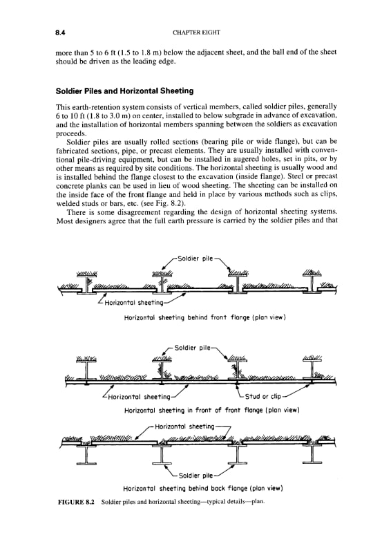
When lagging is installed, there usually is no excavation behind the back flange of the soldier beam. Lagging is usually installed behind the front flange or is attached to the front of the front flange.
Please find the attached image:
Horizontal_sheeting_behind_back_flange_page-0001_fcvhzr.jpg

This is from Handbook of Temporary Structures in Construction by Robert T. Ratay.
 
If you look at the newest, 2012 edition of Ratay's book, I am the co-author of Chapter 7, Earth Retaining Structures. There is a lot more info in the 2012 Chapter 7 than in Chapter 8 of the edition you have.
How deep is the existing building on the left side? Is there a basement? If the left side of your Section B-B is that much higher than your right side, you probably cannot use cross braces, unless they can line up with the floor levels of the existing right side building. Even then, the neighbor probably will not allow you to brace to their building. You may need to use inclined raker braces for both sides.
If you cannot underpin, cannot use tiebacks, and cannot cross brace to another building; the project has a major problem - unless you can design very stiff, cantilevered, secant pile foundation walls that will not need temporary tiebacks or braces. This would involve significant redesign of the proposed building.

 
Although lagging can be installed behind the back flanges of the soldier beams, it is not done very often, except maybe for the upper few feet of the beam where the lagging may need to be removed and the top of the beam may need to be cut off. Soldier beams are usually designed as being fully supported in their weak direction y-axis because there is usually soil or fill concrete and lagging on either side of the web. If you lag behind the rear flange, you lose this lateral support and you will need to use lower allowable stress when designing the soldier beam.

 
PEinc said:
If you lag behind the rear flange, you lose this lateral support and you will need to use lower allowable stress when designing the soldier beam.
I think we need lagging behind the rear flange not to lose lot area. Does that mean pre-loading will be non-beneficial? Can corner struts and horizontal cross struts be used without pre-loading? My thought is that pre-loading can be applied by calibrating the pre-loading jacks after each lagging phase to engage the passive condition. Am I right?
 
@ hoshang
we seamed to be in working at the same region, send your info to my email
---> lazem02(at) gamil and will help you out as much as possible ...
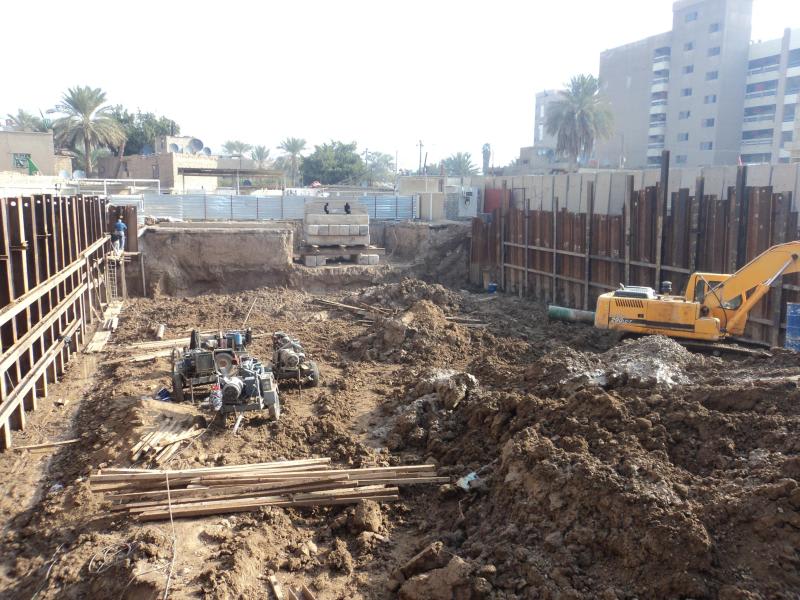
check following picture of similar work i did before
1601337378860_qvqkjk.jpg
 
hoshang, how do you think you will be abke to install horizontal reinforcing steel through the webs of very closely spaced soldier beams? The more you explain and question, the more concerned I am about what you are trying to do. Get help.

 
PEinc said:
hoshang, how do you think you will be abke to install horizontal reinforcing steel through the webs of very closely spaced soldier beams?
My mistake. I didn't consider horizontal reinforcing steel of the basement wall. It seems the underpinning approach of earth retention would be the best choice for my case. Till now the neighbors didn't agree intrusion into their ground. If we make them agree explaining the risks of collapse of the soil under their foundation in case bracing didn't work perfectly, didn't underpinning 8m deep need bracing or anchorage?
ALK2415 said:
we seamed to be in working at the same region, send your info to my email
Please check your email box.
 
Generally, any underpinning supporting about 2.5m to 3m of unbalanced earth pressure will need lateral support. I expect any underpinning for your project would need tiebacks or bracing.

 
Status
Not open for further replies.

Part and Inventory Search

Sponsor