Continue to Site

Eng-Tips is the largest engineering community on the Internet

Intelligent Work Forums for Engineering Professionals

  • Congratulations KootK on being selected by the Eng-Tips community for having the most helpful posts in the forums last week. Way to Go!

Behaviour of sandwich composite plate subjected to blast load

Status
Not open for further replies.

Tony 97

Aerospace
Apr 23, 2024
6
Screenshot_2024-06-19_105339_c2ssyj.png


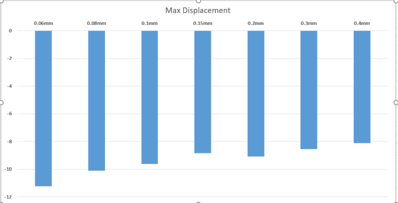
In the sandwich composite plate comprised of ceramic, honeycomb and composite layup sequence, the variation of honeycomb thickness is done and rest all the parameters as same. For the same blast load and same boundary condition, there is a sudden behavioural change for the thickness of 0.15mm. Modelling the honeycomb layer and composite layer as shell and ceramic as solid. Can anyone able to explain this sudden behavioural change. I redo the simulation for more than 2 times and got the same graph.
 
Replies continue below

Recommended for you

"sudden" is a relative word, "discontinuous" may be better ? if you plot the x axis with values (the equal spacing looks like a "criteria" axis) you may get a more reasonable trend. maybe thickness^3 (like moment of inertia), maybe log ?

what is the vertical axis plotting ?

Is there a change in how the panel responds ?

how have you modelled the adhesive (between the facing and the core) ?

This is, to my experience, an exotic lay-up. do you have company testing to validate the FEA ? or is this to happen later ?

"Hoffen wir mal, dass alles gut geht !"
General Paulus, Nov 1942, outside Stalingrad after the launch of Operation Uranus.
 
there is nothing "sudden" in that plot.
a lot more detail is needed.
modeling the honeycomb core with a shell element is likely not accurate at all.
please show a sketch of your actual cross section with dimensions.

 
The vertical axis plot gives the displacement attained by the composite for different thickness of honeycomb. For bonding between the plates, I gave the tie constraint for the case of adhesive. The validation of this FEA is done later by the company. It's just the behavioural study of the plate for different thickness of honeycomb core subjected to same blast load and same boundary conditions.
My doubt is, if I plot the trendline, it is not linear and this pattern gets repeated after certain intervals. For increasing the honeycomb core thickness of certain value, increase in the value of displacement is inferred which alters the trendline to be non-linear
 
it is probably an artifact of either a) the mesh density, b) the numerical convergence, c) how the core is modelled (as I said above, core should be modelled with solid elements not shell elements for this type of analysis)

 
he does say "Modelling the honeycomb layer and composite layer as shell and ceramic as solid" ...

yes, ...

1) very little "sudden behavioural change" ... based on what we're seeing. OP may be commenting on something else he sees in the analysis.

2) It would be more meaningful to plot the x-axis as "specific stiffness" ie MoI per inch width as I suspect it is non-linear. The y-axis is displacment ... times 10^3 ? (I mean what does "-10" mean ?) Are these displacements large compared to the thickness of the panel ?

3) how did you model the adhesive between the facing and the core ? A simple way would be rigid (using the same nodes for the facing as the core OML) but this would lose some stiffness. Maybe model the core as 3D and the facings as 2D shells offset by thk/2 ? But I think the adhesive plays an important role ... possibly not in this very dynamic loading ?

4) are you running time domain loading (surely not static load) ? with geometric non-linearity, material non-linearity ? large displacement ?

"Hoffen wir mal, dass alles gut geht !"
General Paulus, Nov 1942, outside Stalingrad after the launch of Operation Uranus.
 
Is it experimental data that is being plotted or is the plot an output from a simulation? If it is real data, this type of discontinuity would be expected from a delamination of the skins as the panel deflection causes exceeds the capability of the adhesive. The delamination causes the panel stiffness to decrease, and thus the deflection increases.
 
Status
Not open for further replies.

Part and Inventory Search

Sponsor