Continue to Site

Eng-Tips is the largest engineering community on the Internet

Intelligent Work Forums for Engineering Professionals

  • Congratulations KootK on being selected by the Eng-Tips community for having the most helpful posts in the forums last week. Way to Go!

[Belled Cassion] What is the proper way to calculate Ultimate load of a belled cassion? 3

Status
Not open for further replies.

Kevin Lu

Civil/Environmental
Jul 7, 2023
9
Dear Engineer friends,
I'm having an intern at my current company.
My boss gave a task on checking if the belled caisson foundation system can or can not support the warehouse upon it.
The belle caisson has spec of bottom diameter = 48", column diameter = 16", belled section angle = 45 degrees. and the overall height = 11'(exterior foundtion), = 14' (interior foundation)
while the goetech report says the soil around is FAT CLAY (CH) (0=20' under ground) with cohesion of 750 psf - 1000 psf, soil unit weight of 115 pcf, water level at 17' under the gorund.
I'm using the Ultimate Capacity equation to get the individual maximum load of the caisson.
Ultimate capacity of the belled caisson = ultimate end bearing capacity + ultimate skin friction - unit concrete weight of the caisson.

Since the resource that I found was in SI unit system, I transferred all values into kpa and kN.
Since the adhesion factor is not given, I use 0.5 as the adhesion coefficient, and used 0.150 kip/pcf for the concrete density.

In values I got 96.36kip * 30 = 2900 kip < (3120 kip)
After my calculation, my result shows me that 30 caission system (18 exterior caission, 12 interior caissions) is not able to hold the building system (steel frame 140 kip, concrete slab 1320 kip, live load 1660 kip).

But my head engineer said that I used wrong way to calculate the caission.
what is the proper way to calculate?
 
Replies continue below

Recommended for you

The geotech report should stipulate the founding depth and the ultimate strength of the soil as well as the working stress of the soil (in these environs ULS and SLS, respectively). You need to know the axial load and moment applied at the top, both ultimate and working). You then size the caisson for the loads. My SMath program allows you to include the weight of the concrete, exclude it, or to use a density equal to (concrete-less soil). It depends on what is common in your locale.

You size the caisson based on the load and bearing for both ULS and SLS, and pick the bigger one.

As far as the moment goes, you design the shaft for this moment using any number of post-moment calculations. You should consult with the geotekkie on this. The length may be an issue, but I usually exclude any influence of the bell (it's considered as straight shaft for moment).

You can check with the geotekkie about using skin friction and bearing. I often don't, due to the differences in stiffness... geotekkie can advise you.

16 is likely the min dia for a 48" bell... often 2.5 x shaft dia.

Load / allowable bearing = area... and that's about it.

Remember when you place concrete in the caisson, to mechanically vibrate it... in these environs, I've had 40' long caisson concrete drop a foot when vibrated.

750 psf is high for cohesion...

conversion from kN to kips is 1/4.448 (1 kN = 0.225K approx)

-----*****-----
So strange to see the singularity approaching while the entire planet is rapidly turning into a hellscape. -John Coates

-Dik
 
Thanks for your reply,

the warehouse has unevenly distributed live load, since it's designed for storaging different types of chemical in totes. (IBC regular tote: 48" L x 40" W x 46" H)

is there a way to avoid calculation of point axial load? The point load of (based on the current chemical location design) the warehouse varies between 100 psf to 500 psf (IBC suggestion LL = 350 psf) . Am I able to use the average point load (300 psf) as the axial load?

coefficients and values towards moment calculation is not given, is this moment the foundation column's moment or the slab/grade beam moment? Should I also conduct shear checks for the column?

Is there any other ways to calculate the belled caisson allowable load? I feel like that too many coefficients or values are missing.

Is there any online/educational resource to review the belled caisson section? I currently have the IBC 2021, ACI 318-19 (22), AISC Steel Manual (2011) and ASCE 7-16 code in my hands. Different codes are using different system/calculations, Which one has the US standard code?

Thank you for your advice on vibrating the concrete. I'll be aware of it when I get to the on-site section of work.
Thank you for your patience, I'll keep learning through my internship and school courses.
 
Is it a structured slab? or a slab-on-grade? If the latter, then the loads don't go down to the caissons.

If a structured slab, for the level of load, then closely spaced friction piles may be a better solution. An array of friction piles at 12' centres may be in order. What is the depth of your clay?

If you use end bearing caissons, do they need to be inspected. If they do, then a 30"dia shaft may be minimum, and they may have to be sleeved.

If a warehouse, your loads appear to be extremely high.

-----*****-----
So strange to see the singularity approaching while the entire planet is rapidly turning into a hellscape. -John Coates

-Dik
 
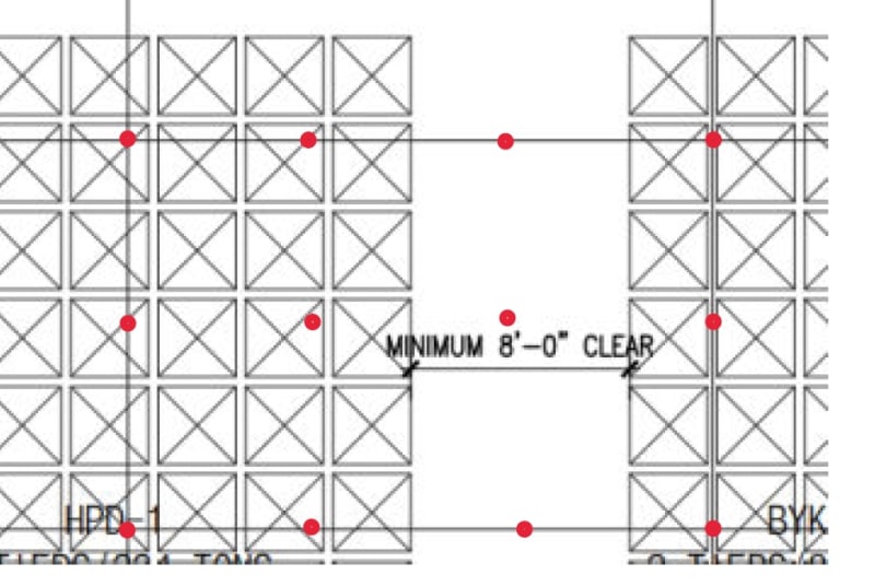
Here's the image that I screenshoted from the building drawing. I think it's the structural slab.
The geotech report recommend the foundation (caisson)'s column to bell diam ratio to be 3:1.
"The recommended bell to shaft ratio is 3:1
 In case of borehole sloughing, bell to shaft ratio required to be 2:1 ."
The report also mentioned that the Allowable Net Bearing Pressure, psf for the Drilled and
Underreamed Piers with Minimum 12 feet below existing grade equals 4500 psf.
 
 https://files.engineering.com/getfile.aspx?folder=7f383d24-9399-4be9-a642-15fc57aafaae&file=Warehouse_Drawing___Soil_Identification.pdf
If structured, your loads are too high for having caissons at column locations. Friction piles in the pattern shown will likely be better. The structured slab will be a lot thinner. Check with the EOR. You may need caissons at the column locations, or maybe longer friction piles. Friction piles are a lot less costly than caissons. If you can use friction piles at column locations, keep the same diameter and go longer... it's less costly to make them longer than to change augers. I normally reinforce friction piles with a single 15M (#5) and at the columns you may want to use 4 - 10M (#4) vert bars.

The bell size may be noted as a max of 3 times diameter. Some 'spreaders' do not do 3x and may only do 2-1/2 times...

Clipboard01_ahjmnw.jpg


-----*****-----
So strange to see the singularity approaching while the entire planet is rapidly turning into a hellscape. -John Coates

-Dik
 
Kevin Lu said:
Ultimate capacity of the belled caisson = ultimate end bearing capacity + ultimate skin friction - unit concrete weight of the caisson.

With belled piles, some say that skin friction should not be included because to get full end bearing, settlement has already taken place, so friction is no longer available. It's probably not quite as simple as that in reality, but that is the rule I have always used. It is conservative as hell, but that's okay with me.
 
Thanks BART... good to get other information. I don' t include skin friction with belled piles or with caissons. Foundations are not the area where I want to save money. In these environs, caissons are generally bearing on limestone, hence the comment about stiffness. Any comments about how to support the loads?

-----*****-----
So strange to see the singularity approaching while the entire planet is rapidly turning into a hellscape. -John Coates

-Dik
 

In reviewing the material, as a result of BART's comment, I missed a point... alternate loading may likely be a real issue if there is a possibility that the loading may be different in the future. With really high live loads this can be a problem. I usually use 2 span bottom reinforcing for continuity. I'll post a detail and you may want to use two span top reinforcing (it's like bottom, but covers top mats. I don't have a detail for that. I only have a detail for oneway with the 2 span reinforcing. For high staggered loads, the cut off points should be determined and those shown are likely inappropriate. The end span dowel should be extended to the end of the first interior mat).

Deleted Image


-----*****-----
So strange to see the singularity approaching while the entire planet is rapidly turning into a hellscape. -John Coates

-Dik
 
Modified a tad...

Clipboard01_hg1xsu.jpg


-----*****-----
So strange to see the singularity approaching while the entire planet is rapidly turning into a hellscape. -John Coates

-Dik
 
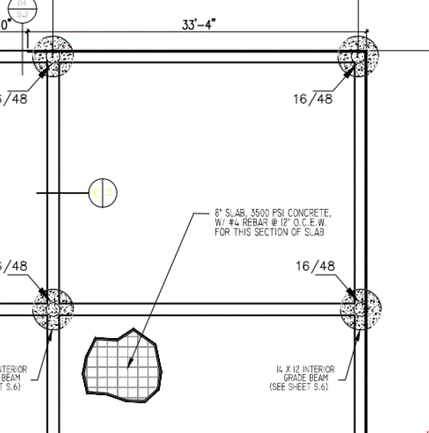
A variation in uniform live load of 100 to 500 psf is huge. Variable live loads are not shown on the drawings presented to date. The snip below seems to indicate typical reinforcement for the slab, which would suggest typical live load throughout. Belled pile sizes would suggest the same thing.

Capture_nb5acg.gif


First, determine what the design live load should be for each area of the floor. Without that, we are just spinning our wheels.

Is this an existing building, or is it a set of drawings for a building not yet built?
Is there a recommendation in the soil report for depth and bearing resistance of belled piles?
 
Thanks Dik and BART,

The building is a bottom up building located in suburban area of Beaumont, TX. The soil report provide a undereamed pier depth of minimum 12 fts under existing grade, with a Allowable Net Bearing of 3000 psf (DL + Sustained LL) and 4500 psf (total DL+LL).

I have all of the drawings and reports in my hands, but I'm quite worried about the copyright issues. I can screenshot these drawings if needed. (Soil report is attached)

Most of the floor (each 30' x 20' area) has a chemical tote live load of 40-48tons, maximum load (floor area) reaches 52 tons, in psf the range is (160psf - 200 psf) for chemical storages.

For Dead load, assuming using normal concrete density (150 pcf), for each floor area (30' x 20'), slab weight approximately equals to 0.150k/cf * (8"/12)*(30'x20') = 400 cf * 0.15 k/cf = 60kips /(600sf floor). Aka. 100 psf.
For the 16/48 Belled caisson, each weight equals 0.15k/cf *{(pi * (16"/12/2)^2 * 12') + 1/3 * pi * (16"/12) * [ (48"/12/2)^2 + (16"/12/2)^2 + (48"/12/2) * (16"/12/2)]} = 3724 pounds/12' 16/48 belled Caisson.
My boss said that the Steel Company had already include the windload and seismic load in the steel frame report. Steel frame has a load of 117000 lbs with 15% overcounts equals around 140000 pounds. Average this load to all floor area equals 9.33 psf.
Since the steel frame only connect to the exterior foundation columns, should I only counts the steel frame load in exterior column load calculations? if the steel frame loads only on exterior foundations, then each caisson with support a load of 140kips/18 caisson = 7.8kips /caisson.

What else do I need for the foundation calculations?

My boss is heading to the site next week. He will check the drawings again with the on-site engineers.

Thanks again for your help.
 
 https://files.engineering.com/getfile.aspx?folder=4d234485-330a-4dfe-8678-6c147e8195ef&file=HM_Plant_-_Geotech_Report.pdf
At school, I've been taught using a standard series of load calculation based on ACI 318-19 code.
Start with footing area calculation, with DL LL, service load, soil bearing, all densities, comprehensive strength, and all coefficients.
Then I will get a footing sample dimension from there. (usually "(D+L) / soil bearing capacity" for spread squared footing width)
Then, I need calculate the Factored Net soil Pressure: Qn= (Pu/Ag) ending with k/ft
Then, I start the one-way shear check from there:
One-way Shear:
H = Foundation Thickness - deck thickness
D = thickness - cover - dbar - top layer
Vu = Qn * Footing thickness * (½ footing width - ½ foundation column width - D)
Vc = Φ * 2 * sqrt(f’c) * footing width * d
Then check if Vu < ΦVc, PASS.
If needed, flexture check can be conduct from here.
But these seems only work with regular column spread footing.
How about this belled caisson?
My friends at school said just use net allowable bearing (4500 psf) times the bottom bell area (12.56sf) to get the belled caissons' ultimate load.
But I don't think that's right. What should I do?
 
Kevin Lu said:
My friends at school said just use net allowable bearing (4500 psf) times the bottom bell area (12.56sf) to get the belled caissons' ultimate load.
But I don't think that's right. What should I do?

The allowable (not ultimate) load is 4500*12.56 = 56,520#, less than the dead load of the floor. The capacity of a belled pile cannot include skin friction, because skin friction is no longer available after the bearing pressure is reached.

The piles cannot sustain specified live loads. The ground floor, as a structural floor, cannot sustain specified live loads. A 3'-0" depth of compacted select fill is shown on Section 1. The ground floor is clearly intended to act as a grade supported slab, not a structural slab. The piles are intended to carry the roof structure, but not the floor with its heavy live loads.

Is it prudent to tie the floor slab into the piles? Or is it better to separate the floor from the piles? If the rise or fall of the floor system is limited to one inch, it may not matter; if the rise or fall is three or four inches, the owner is not likely to be very happy.

What should you do? Consider the existing design carefully, then advise your boss of your conclusions.
 
A closer spacing of piles as suggested earlier by dik, should be considered. Whether belled or friction piles should be used is a geotechnical consideration. If the ground floor live load is to be carried by piles, a closer spacing is needed; this could help in resisting swelling pressure as well. A flat slab could be used without the orthogonal system of beams; it could be reinforced to resist both live load and uplift pressure from swelling clay.

If live load is to be carried by a grade slab without pile support, the slab needs to be properly reinforced top and bottom in order to accommodate the large live loads without excessive cracking. This is a more economical option than using pile support, but differential settlement can be expected, the magnitude of which is difficult to estimate.
 
A mat foundation should also be considered, omitting all piles and grade beams. The footprint of the building would be excavated to a depth of three or four feet to accommodate the special fill (which I assume would be granular). The columns, carrying only the relatively light roof load would bear directly on the mat foundation.

This seems to be a very clean solution and may well be the most economical.
 
Status
Not open for further replies.

Part and Inventory Search

Sponsor