Continue to Site

Eng-Tips is the largest engineering community on the Internet

Intelligent Work Forums for Engineering Professionals

  • Congratulations SSS148 on being selected by the Eng-Tips community for having the most helpful posts in the forums last week. Way to Go!

Bending Capacity of Plate 1

Status
Not open for further replies.

Vrpps EIT

Structural
Aug 21, 2018
58
Hi All,

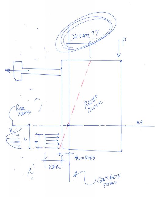
Attached a detail, where a steel saddle is welded to a plate which in turn is fastened to Concrete wall with anchors. As the saddle is welded to plate it creates a moment there also the plate at the top (1/3) is left free as the concrete wall is below the top height of the plate.
1. In this scenario should the plate be checked for its bending capacity as it experiences a tensile pull at the top duet to the moment, if so how to calculate the resisting moment capacity there?
2. Irrespective of it should it be restrained at the top free part by connecting it back to the foundation wall with the gusset plate?
3. I hope the bolts here are only for shear transfer? or does it have to be checked for its tensile and pull out capacity caused by the moment at the top

Thank you guys!
 
 https://files.engineering.com/getfile.aspx?folder=1e16b1fe-3e87-46cf-b5dd-327e6bf41887&file=Scan001_(3).jpg
Replies continue below

Recommended for you

You're welcome. Make no mistake though: this is something that I'm only, say, 55% confident about. I'm asking as much as telling on this.
 
KootK said:
2) Being able to strain the concrete to 0.003 is predicated on being able to strain the anchor/reinforcement to 0.002.

This is one part that I can't seem to wrap my head around intrinsically. Which seems really ridiculous to say as a practicing structural engineer.


Separately, I've been running some numbers with Hilti KB3s... most anchors reach 30-40% of yield at the allowable load limit and yield at the ultimate load. (Assuming no edge distance or spacing concerns, NW 4ksi concrete). So I wonder whether being governed by a ductile failure mode and ductility in service are two separate distinctions, at least in idealized circumstances.

----
just call me Lo.
 
Lomarandil said:
This is one part that I can't seem to wrap my head around intrinsically. Which seems really ridiculous to say as a practicing structural engineer.

Don't lose any sleep over it. I've reconsidered and believe that I may well be wrong about that statement. I retract it until further notice. Carry on believing yourself to be competent.

I believe that I can, however, articulate the source of my confusion if you'll indulge a friend with a mental experiment.

What is fundamentally incorrect about the story that I'm trying to tell below?

In my heart of hearts, I don't actually feel that an anchor of this sort is capable of any meaningful strain the same way that rebar is. Rebar strain mostly happens between cracks. And, obviously, such a crack is the very end of an anchorage scenario. Perhaps it's altogether wrong of me to be thinking of these things in RC concrete design terms.

c01_rhm2o1.jpg
 
KootK said:
n my heart of hearts, I don't actually feel that an anchor of this sort is capable of any meaningful strain the same way that rebar is.

Is the right story this maybe?

c02_cidyzn.jpg
 
Overall, I agree with KootK.

There is no assumption about the steel strain in "conventional reinforced concrete flexural analysis". The concrete strain is assumed to be 0.003, and the steel strain is governed by a number of factors including concrete strength, steel area, steel strength, and cross sectional geometry. The phi factor equation is based on the steel strain, which can vary (below).

Having said that, in most cases, the steel strain is near or above the yield strain.

I think the big thing is that in "conventional reinforced concrete flexural analysis" you are finding the plastic strength of the section or the strength at failure, you aren't calculating the tension in the bar at a given loading.

By assigning a moment and assuming a concrete strain, you are over-defining your system and you won't be ensuring stain compatibility. You need to either assign a moment (what we're trying to do here), or assign a concrete strain ("conventional reinforced concrete flexural analysis" - which is not useful for this exercise).

So then the real question becomes, what should the shape of the stress distribution look like, and triangular seems to be the most reasonable since the concrete will likely be far away from crushing, and you will have a much longer "C" zone than for "conventional reinforced concrete flexural analysis".

ACI_318_Table_21.2.2_pqnlfm.jpg
 
chris3eb said:
you are finding the plastic strength of the section or the strength at failure, you aren't calculating the tension in the bar at a given loading.

YESSSS!!!! And that is huge. Thank you for that. This concept was rattling around in my brain but was't quite fully formed until I saw your post.

It'll take me some time to digest the rest but your whole explanation was very insightful. The over-constraint business speaks to the mathematician/logician in me.

I've been trying to dig up some stuff on the fancy, Eurocode "component" method. Stilling seeing a lot of little rectangular stress blocks...
 
I wouldn't normally put too much weight into what Profis has to say, but I threw a plate into Profis with just a 10,000 in-lb moment on it and this is what it gave me:
Tension = 1265#, max concrete stress = 355 psi, C=1.8" (through scaling), and B=4" (I assigned the plate width). With that, if they were using a triangular stress distribution, you would end up with Compression = 1/2 x 355 psi x 4" x 1.8" = 1278#

Based on a triangular distribution starting at zero at the anchor, you would get T = 10,000 in-lb / (2/3 x 8.5") = 1765#
Based on saying the center of compression is 1" above at the bottom of the plate (because why not), you would get T = 10,000 in-lb / (8.5"-1") = 1333#

Strictly following the stress block method, for 3000 psi concrete, you would say a = 1265#/(0.85 x 3000 psi x 4") = 0.124", and T = 10,000 in-lb / (8.5"-0.124"/2) = 1185#

So at least as far as Profis is concerned, the stress block method is slightly unconservative, the full triangle is pretty conservative, and the super lazy way is pretty right-on.

Profis_Output_hgtqin.jpg
 
Whether the full area of plate will be bearing on surface or not, Isn't it determined from comparing the eccentricity of load with kern?
For small eccentricity, I'll agree with what KootK is saying.
For large eccentricity, I'll agree with what Lo is saying.


Euphoria is when you learn something new.
 
Is that a 1/2" anchor in the profis analysis? I tried to back-calc but imperial is not my mother tongue.

I think profis probably does a typical compression-bending interaction analysis with a full stress-strain curve for the concrete. Iterate neutral axis location and concrete strain until the axial and moment reactions match the applied loads.

Can't have the neutral axis at the location of a single anchor for a pure bending case as there's no stress on the anchor for that case (Hooke's law).
 
steveh49 said:
Can't have the neutral axis at the location of a single anchor for a pure bending case as there's no stress on the anchor for that case (Hooke's law).
Agreed. Zero strain at steel means it will not be in tension. For pure bending, tensile strain will be greater than zero at anchor bolt.

Euphoria is when you learn something new.
 
Come on guys, give me a little credit . Of course I am aware of Hooke's law and its implications. The idea was not to suggest truly zero strain but, rather, very little strain such that zero strain becomes a simple, reasonable approximation.

How much strain do we think can be had in a system like this that has a very short length and is usually governed by concrete tensile failure? Seriously, how much and how do we estimate it?
 
Blackstar said:
Whether the full area of plate will be bearing on surface or not, Isn't it determined from comparing the eccentricity of load with kern?

I think that this is trivial for this discussion. If there isn't plate lift off then there isn't anchor tension and little that we're discussing here applies.
 
Why is the short length an issue for strain? Or do you mean elongation? For 200MPa (say) on 200mm long headed anchors, the elongation is 0.2mm. Less for bonded anchors because the stress reduces over their length.

I'm not sure yet why we're on different pages but the concrete is failing in tension as you say so the anchor is strained sufficiently to cause that tension.
 
I'm thinking of determining the stress in steel by finding NA using elastic theory and fixing the stress in concrete to allowable stress.
IMG_20200223_173111_mhjqd4.jpg
 
steveh49 said:
Why is the short length an issue for strain? Or do you mean elongation? For 200MPa (say) on 200mm long headed anchors, the elongation is 0.2mm. Less for bonded anchors because the stress reduces over their length. I'm not sure yet why we're on different pages but the concrete is failing in tension as you say so the anchor is strained sufficiently to cause that tension.

It'll be a bit of a journey.

1) As I understand it, concrete strains at pure tensile rupture are on the order of 0.0001 to 0.0002. So an order of magnitude lower than steel yield strains.

2) I don't know if anchorage concrete tension rupture strains are similar to #1 but that's my assumption until somebody shows me otherwise.

3) I'm concerned with both strain and elongation as I see them as interrelated here. For steel reinforcing in concrete, we're able to justify steel yield strains primarily because of what goes on between cracks. And, in that sense, strain is dependent upon an elongation length suitable to produce enough cracks to facilitate that strain. In an anchorage situation, I feel that such cracks represent anchorage failure and, thus, we ought to limit ourselves to what ever strain would be present at such an anchorage failure. Based on #1, I worry that this is very small value.

4) I don't know that we're really on different pages given that I don't actually have a definite page yet myself. I'm still feeling things out. I do, however, harbor skepticism that any significant amount of strain ought to be assumed at the anchor. If you feel otherwise, then that is indeed one point of disagreement between us.
 
Blackstar123 said:
I'm thinking of determining the stress in steel by finding NA using elastic theory and fixing the stress in concrete to allowable stress.

I believe that's pretty much the same idea as Lomarandil had suggested. Baring some newfound, silver bullet understanding, I do support that as a sort of "middle road" compromise.

Lomarandil said:
...or at least a "masonry-style" triangular block that doesn't necessarily reach the top bolt...
 
Status
Not open for further replies.

Part and Inventory Search

Sponsor