Continue to Site

Eng-Tips is the largest engineering community on the Internet

Intelligent Work Forums for Engineering Professionals

  • Congratulations waross on being selected by the Eng-Tips community for having the most helpful posts in the forums last week. Way to Go!

Bending moment acting on an aircraft rib 2

Status
Not open for further replies.

jcdt94

New member
Feb 26, 2022
2
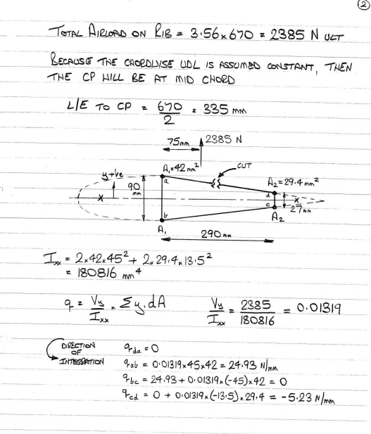
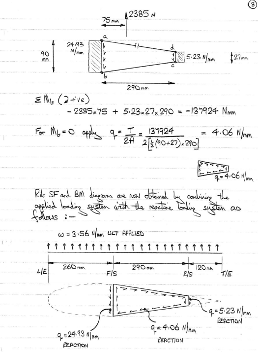
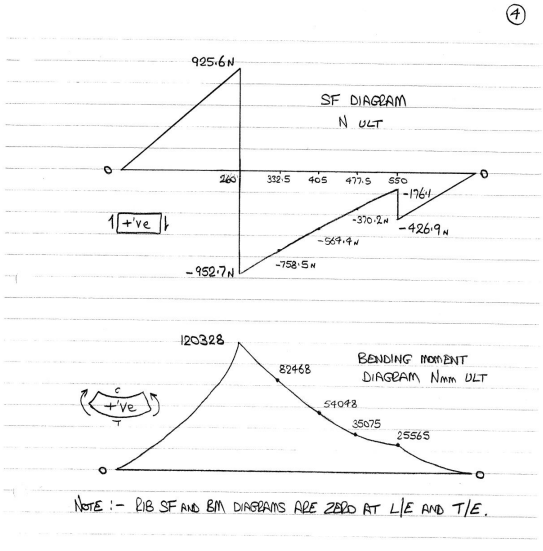
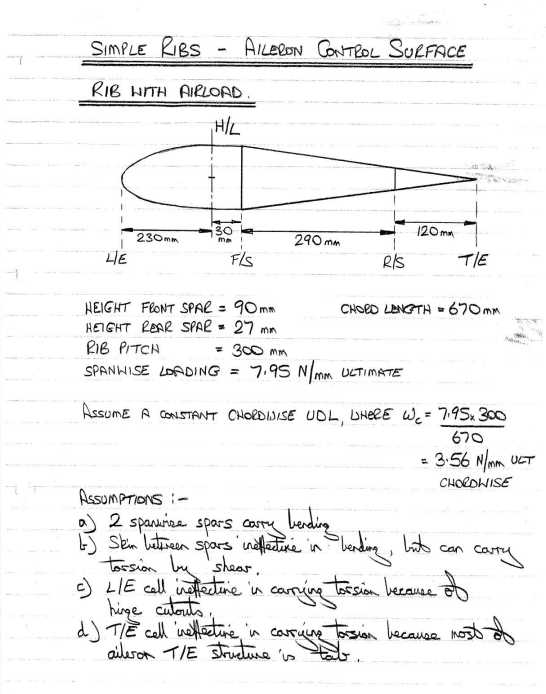
Hello friends, I am having trouble with the estimation of the bending moment acting on an aircraft rib. The method shown in the images attached was given by a teacher at the university. I know how to do all the calculations up until the bending moment diagram, there I am struggling, since that was I've drawn bending moment diagrams was to use the areas under the curve of the shear diagram, but for this case that doesn't seem to work, or maybe I am doing something wrong ( most likely).

I really don't understand where the bending values are coming from.

Thanks in advance my friends
1_lzy87i.png
2_opkce1.png
3_zmkhmo.png
4_xs6ugo.png


Replies continue below

Recommended for you

Look at the rib freebidy - The skin shears contribute to bending moments, not just the vertical shear.
Once you account for the skin shears your BM plots should make sense.

 
rather than a rib in bending, think of the rib as three torsion cells. The shear flows in the skins balance the shear in the spar webs.

This problem looks suspiciously looks a student problem ?

another day in paradise, or is paradise one day closer ?
 
RB... This IS a university student...

"...The method shown in the images attached was given by a teacher at the university. …"

Regards, Wil Taylor
o Trust - But Verify!
o We believe to be true what we prefer to be true. [Unknown]
o For those who believe, no proof is required; for those who cannot believe, no proof is possible. [variation,Stuart Chase]
o Unfortunately, in science what You 'believe' is irrelevant. ["Orion", Homebuiltairplanes.com forum]
 
It is kinda like a student problem to shows how to initially dimension a light rib, taking the shear force to size the web of the rib and bending for the flange. Just i cannot find the correct bending, the shear diagram is easy, I took the component of the vertical shear in the a-d and b-c sections, but when i try to get the bending i just cannot find the correct one, between a-d and b-c, and thus my diagram doesn't end in 0[dazed].
 
the rib doesn't work like a beam in bending, but like three torsion cells.

please note, student posting is not permitted.

another day in paradise, or is paradise one day closer ?
 
I glassed over problems like this in school cause I knew I'd never be the one doing that... I just figure out how to make stuff. I have Bruhn sitting on my shelf with crisp pages still.
I enjoy seeing this stuff/been afraid to ask sometimes.
 
I wonder how many Bruhns went to their graves with crisp pages ?

another day in paradise, or is paradise one day closer ?
 
I fear mine will. Was never my world. But my 43.13 and machinery handbook have taped spines and coffee stains. If I'm missing my starrett scale its in the thread charts.
 
When we were introducing FEA at LandRover/Jaguar 4 decades ago lucky greg was the one who got to build FEA models of the worked examples in Bruhn and than try and puzzle out what was wrong, ably assisted by my manager, who knew Bruhn backwards.

Cheers

Greg Locock


New here? Try reading these, they might help FAQ731-376
 
I imagine that Bruhn is close to a ROD and shear web model ?

another day in paradise, or is paradise one day closer ?
 
You can get remarkably good correlation between dummy loads method in bruhn article A.?? and cshears and crods.

One takes about an hour to set up and seconds to run. The other takes about a month, but brings far greater satisfaction.
 
I also think something doesn't add up in the bending moment diagram.

The F/S reaction is approx 1878N and the R/S is ~250N. The remaining ~255N comes out as the vertical component of the shear flow in the inclines.

At the front spar, it's just 3.56*260*260/2=120,328N/mm. (Matches)

At 332.5mm, the bending moment is 3.56*332.5*332.5/2-1878*(332.5-260)-4.06*sin(6.2)*(332.5-260)*(332.5-260)=58,310N/mm. (value quoted is 82,468N/mm)
 
Try accounting for the horizontal component of shear flow in the skins, not just the vertical component. I haven't run the numbers on this one, but that is usually where people slip up with these problems.
 
While I get that the reaction system with 4.09N/mm shear flow reacts the torsion, I do not understand what it does to the rib. For example, what if there was no rib in this system (when looking at torsion alone)?
 
Neat topic... wouldn't the bending moment occur because of the lift and the cantilever from the fusilage? or is that the obvious part? [ponder]

Rather than think climate change and the corona virus as science, think of it as the wrath of God. Do you feel any better?

-Dik
 
Dik: this topic pertains to bending in the plane of the rib web, (not wing bending).

Jp: for a wing in pure torsion, if there were no rib at this station, the macroscopic effect would be greater warping of the wing cross section (wing becomes more torsionally flexible), at a detail part level the onset of panel buckling would occur at a lower load.
 
Status
Not open for further replies.

Part and Inventory Search

Sponsor