Continue to Site

Eng-Tips is the largest engineering community on the Internet

Intelligent Work Forums for Engineering Professionals

  • Congratulations waross on being selected by the Eng-Tips community for having the most helpful posts in the forums last week. Way to Go!

Bending of steel angle leg 1

Status
Not open for further replies.

Finite_element

Civil/Environmental
Mar 9, 2018
6
Designing an angle for a temporary bridge bearing keeper angle, in aashto LRFD. One leg is anchored into concrete, I need to size the thickness of angle for bending of the other leg.
Originally I designed it in ASD aashto standard spec, given horizontal load.
Yield stress fy = 50ksi
allowable = 27 ksi (AASHTO Std Spec Table 10.32.1A)
Leg = 4 in
Angle thickness = 0.625
Angle Length = 15 in

I can calculate the moment capacity of this section (=39.6 k-in)
design moment arm is 26.125 k-in calculated, so design checked out in standard spec.

I understand steel bending for aashto LRFD usually has a phi factor of 1.0, but how would I design this in LRFD, besides using factored loads? Is there any LRFD section I should be paying close attention to?

Thank you for any insight!!
 
Replies continue below

Recommended for you

Basically just putting a simple bending force on angle leg, but wondering if there's anything I'm missing if designing in accordance with AASHTO LRFD as opposed to Std spec (other than using factored loads). Thanks again!
Capture_celgfy.png
 
I would expect local crushing of the concrete at the face of the concrete around the embedded leg to affect the point of fixity (and thereby, the moment arm on that leg of the angle. There's also the possibility a breakout failure that should be considered, which I would expect to be the primary failure mode controlling the strength of the keeper.

For these types of situations, we would typically embed anchor bolts and attach the angle to those.
 
There is no embedded leg. There are anchor bolts embedded into the concrete and bolted at the bottom leg of the angle. Sorry if I was unclear.
I just wanted to do a quick additional check for bending. Thanks again for input.
 
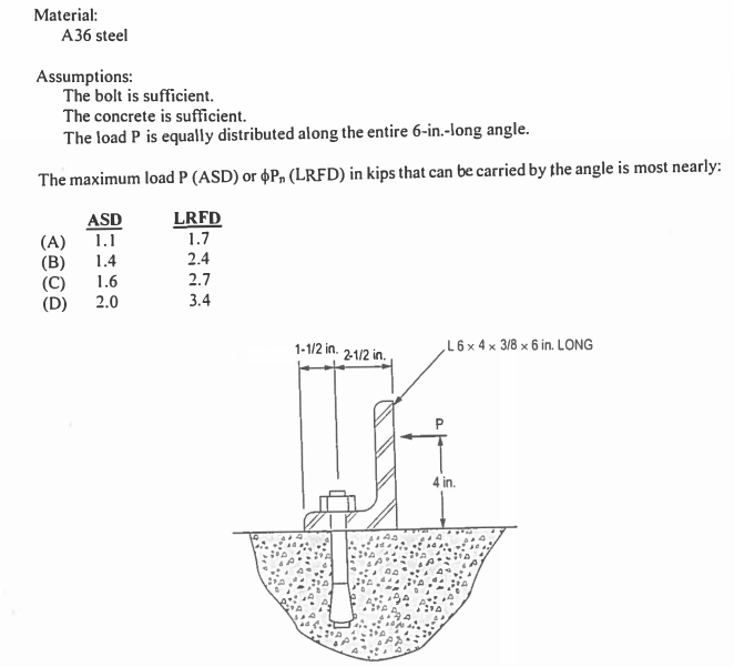
Check out section 6.12.2.2.7 (Nominal flexural resistance of miscellaneous flexural members). Interestingly enough, I remember this exact scenario being a practice problem for the PE exam.
SNIP_bbwtvm.png
 
In my experience, the main thing is to be careful when determining the effective width of the bending plane of the angle. Maybe for a short angle like this, you can assume the whole 15 inches, but that may be overly conservative depending on how the load is applied.
 
Wow, that practice problem is spot on. Thanks for all the help!
 
I'm gonna get myself in trouble here - Is there a reference in AISC for how to calculate something like this? I've always designed connections like this taking the section modulus of the angle leg at typical thickness, and using an extra inch of leg to each side of the load, if applicable. I'm looking at the practice problem, and coming up with .8k for ASD using this/my method - so looks like a substantial overdesign...
 
Status
Not open for further replies.

Part and Inventory Search

Sponsor