Continue to Site

Eng-Tips is the largest engineering community on the Internet

Intelligent Work Forums for Engineering Professionals

  • Congratulations KootK on being selected by the Eng-Tips community for having the most helpful posts in the forums last week. Way to Go!

Bending stress classification - corner of double wall rectangular vessel 1

Status
Not open for further replies.

Jorge Pena

Mechanical
Feb 22, 2023
2
I would like to receive some advice about bending stress classification in the corners of a rectangular or parallelepiped double wall vessel with ligaments. Code: ASME VIII-2 5.5.2 or EN 13445-3 Annex C 
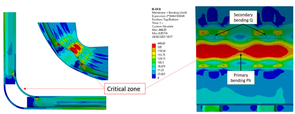
Imagen1_hk62nl.png


From my analysis, this zone can be compared with a flat head - junction to shell from VIII-2 Table 5.6. It is classified as primary (Pb) if the bending moment is necessary for maintaining the bending stress in the center region within acceptable limits, otherwise it is secondary (Q). 

I know that there is a superposition of primary+secondary in this zone since ligaments locally constraint displacements. Finally, the stresses has been classified as Pb between ligaments and Q near the ligaments in order to be conservative. However, may it be possible to classify all bending as secondary (Q)? 

It would be valuable discuss this case with someone else.

Thank you in advance.
 
Replies continue below

Recommended for you

I will refer you to paragraphs 5.2.1.2 and 5.2.1.4 in ASME Section VIII, Division 2:

ASME Section VIII said:
For components with a complex geometry and/or complex loading, the categorization of stresses requires significant knowledge and judgment. This is especially true for three-dimensional stress fields. Application of the limit load or elastic–plastic analysis methods in 5.2.3 and 5.2.4, respectively, is recommended for cases where the categorization process may produce ambiguous results.

ASME Section VIII said:
The structural evaluation procedures based on elastic stress analysis in 5.2.2 provide an approximation of the protection against plastic collapse. A more accurate estimate of the protection against plastic collapse of a component can be obtained using elastic–plastic stress analysis to develop limit and plastic collapse loads. The limits on the general membrane equivalent stress, local membrane equivalent stress and primary membrane plus primary bending equivalent stress in 5.2.2 have been placed at a level which conservatively assures the prevention of collapse as determined by the principles of limit analysis. These limits need not be satisfied if the requirements of 5.2.3 or 5.2.4 are satisfied.

On the basis of the information that you have provided, it appears that your specific case seems to be generating ambiguous results. Therefore, the recommendation in paragraph 5.2.1.2 ought to be followed.
 
Appendix 13 of Div 1 uses elastic stress equations to find minimum thicknesses for rectangular vessels, including the corners.
Perhaps, you could use the allowerble stresses from that to design using elastic analysis.
It would depend on the effects of the ligaments between the two walls.
 
ASME VIII-1 Appendix 13 is limited to single-wall vessels acc. to 13-1(a) & 13-2. I would only use App. 13 to estimate the thickness before using U-2(g). Maybe you wanted to refer to the same thing.
 
Raul, it would be a U-2(g) design, where Appendix 13 equations and design margins are the basis of the design (not the initial estimate). FEM wouldn't be needed. Just beam calculations (probably iterative). It would require judgement, and the right geometry.
 
Status
Not open for further replies.

Part and Inventory Search

Sponsor