Eng-Tips is the largest engineering community on the Internet

Intelligent Work Forums for Engineering Professionals

  • Congratulations waross on being selected by the Tek-Tips community for having the most helpful posts in the forums last week. Way to Go!

Best approach for (file > points > closed curve) to make two curves, then (curves > ruled > body)? 1

Status
Not open for further replies.

please_dont_crash

Automotive
Apr 21, 2020
25
0
0
US
Hi!

I'm pretty inexperienced with NX so I wanted to hear your thoughts on the best way to approach this task.
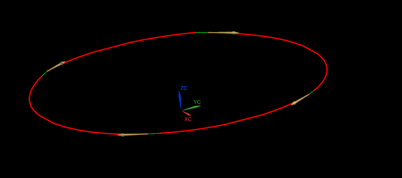
See image here.

[ul]
[li]I want to generate a volume that connects two closed curves, let's call these curves A and B.[/li]
[li]I think I will probably be using Ruled to create this volume.[/li]
[li]The coordinates for the points in A and B come from two different files.[/li]
[li]Curves A and B both lie on parallel planes, but this is likely not relevant.[/li]
[li]Curves A and B have the same number of points, N. Please note: N might be large, so manual per-point operations should be avoided.[/li]
[li]The curves are made up of straight line segments, not splines.[/li]
[/ul]

I think that's about it.

I already have experimented creating a text file, A.asc with some X Y Z coordinates, and they import as non-timestamp geometry. If I import the second file, they all get lumped together in a non-descript way, so I think I need to make my curve before importing the second file.

I do not yet know how to make a curve out of points using straight line segments, only a spline, which is not what I want. How can I do this?

I am assuming that Ruled will take curves A and B and generate the volume I am interested in, i.e. solid body. Once this body has been created, I will be performing boolean operations on it.

I am open to using a journal script in NXOpen to accomplish this if necessary.

Please let me know if I've missed something in my problem statement!

Thank you!
 
Replies continue below

Recommended for you

The line definition , how important is it that it is an object of the type "line" ?
In NX, a spline of degree 1 is linear between the defining points. geometrically it should be no difference between for example 5 points connected by 4 lines or 5 points connected by 1 spline degree 1.

I tried using the "fit curve" to simply drag a rectangle around the points to use and then the intention was to 1) tick " closed" 2) set the number of segments = number of points 3) set degree to 1
but NX12 does not allow me to do that..., maybe i am doing something wrong. (?)

There is a "retired type" os spline that probably allows you to fit a closed degree1 to "n" points.

When you create the ruled body ( or use the "Through curves" feature, these will produce the same resulting geometry for most cases but there are minor differences.
You can/ must make sure that you have the starting points of each section "in good places" , imagine putting on a sock on your foot and twisting it.
If you use the alignment option by points you can snap/drag the alignment to a better shape.
I imagine that you want to toggle on the "preserve shape" since you have corners in the sections .


Regards,
Tomas


toost said:
The line definition , how important is it that it is an object of the type "line" ?
In NX, a spline of degree 1 is linear between the defining points. geometrically it should be no difference between for example 5 points connected by 4 lines or 5 points connected by 1 spline degree 1.

Interesting! I very briefly experimented with spline creation based off points and I thought I was not able to reduce the order number below a value of 2 (I think?). So in summary, as long as the points are connected by straight lines and the resulting curve works with the rest of the steps, I'm not particular about how we get there.


toost said:
When you create the ruled body ( or use the "Through curves" feature, these will produce the same resulting geometry for most cases but there are minor differences.
You can/ must make sure that you have the starting points of each section "in good places" , imagine putting on a sock on your foot and twisting it.
If you use the alignment option by points you can snap/drag the alignment to a better shape.
I imagine that you want to toggle on the "preserve shape" since you have corners in the sections .

"Through Curves" has popped up in some of my search results, but I haven't tried it yet. It sounds like I should check it out. Having to manually align points sounds like it would not work very well for a large number of points, though, because there would be some uncertainty about which points go with which.

Thanks for your help!

p.

 
Bumping this thread because I would still like to know how I can, in one action, join multiple non-timestamp geometry points by straight line segments into a closed curve.
 
I realize that I never said how to do this...

If you use the old spline creation tool, it has the ability to create a linear ( degree 1) , multi segment spline.
it's a dialog series that will be retired sometime in the future, ( you will notice why when using it... :) )
Use the command finder ( top right on screen ) search for "spline". Scroll down until you find the one named "Spline (to be retired)"
will start a dialog w 4 buttons : By poles, Through Points, Fit, Perpendicular to planes.
Select the Through points,
tick : Multiple segments, Curve degree = 1, Closed curve = yes ( in this dialog , you can load an ascii file w point coordinates. ) OK
new dialog w 4 buttons , select the "Chain from all" ( NX will search for the next closest point from the one that you select)
new dialog, cue text bottom left corner of screen "Select start point" , pick point in profile.
( remember when selecting these 2 ( or "n" ) series of points to pick this start point "in line" since NX will match these between the sections.)
after selection , NX will ask for end point , pick "the next point" from the start selection
The dialog that appeared before appears again, this time the "multiple segments" and "Curve degree" etc are grey, Press OK.

As said, this feature will be retired sometime in the future, but not before NX has matching functionality in newer/other features.

Regards,
Tomas

 
Thank you, Toost, for that detailed explanation. I have tried it out a few times and I've found that the step where I get to select the start point does not always appear. This is a little disconcerting but in general the button does what I need.

I also decided to try out cowski's suggestion. As usual an NX journal file saves the day. I have edited the code so it closes the the end point to the first point. I think I'll continue working with this as I find it more predictable and extensible should the need arise.

One thing, though. Using the journal method, I obtain lines in the viewport, but I have no features at all in the feature tree. Not even under Non-Timestamp Geometry. Is there a way to end up with a feature or features I can at least select?

EDIT: Taking a look at this currently:


EDIT 2: Ok, looks like that would take quite a bit of reworking the first example. I don't really need the lines as features if I can just build my shape using Ruled, assuming it works. And a quick test with a 10-point file suggests it does work with Ruled.

EDIT3: Looks like when I use Ruled on the lines created by the script, they then become non-timestamp geometry and appear in the feature tree.

EDIT4: And sometimes they appear as N-TG even before using Ruled? But not always?

Thanks!
 
You should be able to double click on a line to edit the start/end points (but they won't be associative to the points you pick). You could certainly create all the lines as line features, but that would slow the process down, bloat the file size, and probably not really add much value in your case.

I'm not sure why the lines are not immediately showing up in the non-timestamp geometry; maybe if we force a model update at the end of the journal...

www.nxjournaling.com
 
I am curious on this. can you tell us a little on what it is that you are doing ?
why do You want lines between the points?

Regards,
Tomas


Thanks for the tip, cowski. I think it is related to the model updating. I haven't been able to work on this since last week but I do remember that there was an action I could take that presumably forced an update, and then they would show. For now it's fine as it is.

Toost, there's not much I can say unfortunately, but it is related to optics. There's really capable optics packages and really capable CAD packages, but for some things, to go between the two you just have to ask the optics people to dump a bunch of points into a file and go from there.

In the end I was successful with the NX Journal approach. Thank you, cowski, again. However, this leads me to another question, which I will post below.
 
Unfortunately I am running out of ideas on how to solve this problem. I realize the topic has strayed a bit from my original question, but I think there's value in keeping everything in one place.

I imported my point file using a script found on NXJournaling.com. I will paste the script at the bottom of this post. The script reads the point file line, creating lines between these points. This worked great for one dataset, and Ruled was happy, and saw each of the two curves as contiguous and sequential. The problem is with my second dataset of two curves. It looks contiguous, but when I select one of the curves (or rather, series of line segments) with Ruled, I get this:

problem_rtgv7b.png


As you can see, Ruled thinks there are 4 curves. Also, Ruled says there are only 200 segments, but my point file contains 248 points.

The points lie very close to the z = 0 plane, so I calculated ATAN2(x,y) and sorted the dataset by that value. That way I am ensuring each line drawn comes after the previous one, tracing out a rough circle. I have even printed out the distance between adjacent points, trying to catch weird jumps, but there's nothing apparently wrong: the distances between successive points changes, but smoothly. The only remark I can make about these distances is that there are 4 instances in the dataset where the points are very close together, on the order of 1E-6 mm. EDIT: I removed the points that created such a short segment and this did not fix the issue.

Any suggestions? Is there a way I can preprocess these ~ 248 line segments into something more palatable for Ruled?

Here is the script:

Code:
'NXJournaling.com
'example: read text file
'each line of the input file should be 3 numbers separated by commas (#.###, #.###, #.###)
'the numbers will be interpreted as line start/end points
 
Option Strict Off  
Imports System  
Imports System.IO  
Imports System.Windows.Forms  
Imports NXOpen  
Imports NXOpen.UF  

Imports NXOpenUI

Module NXJournal

Public theSession As Session = Session.GetSession()
Public lw As ListingWindow = theSession.ListingWindow
Public ufs As UFSession = UFSession.GetUFSession()
Public theUISession As UI = UI.GetUI


	Sub Main()  
	
		'dim myWriter As IO.StreamWriter
		'dim outputFilePath as String = Environment.GetFolderPath(Environment.SpecialFolder.Desktop)
		'Dim outputFile As String = IO.Path.Combine(outputFilePath, "test.log")
		
		'myWriter = My.Computer.FileSystem.OpenTextFileWriter(outputFilePath, False)

		dim mywriter_string As String = ""
		lw.Open()
		Dim firstline as String  = "Counter" & "," & "Atan2" & "," & "Distance from prev" & "," & "x" & "," & "y" & "," & "z" 

		lw.WriteLine(firstline)
		'myWriter.WriteLine(firstline)
		
		Dim openFileDialog1 As New OpenFileDialog() 
		openFileDialog1.Filter = "txt files (*.txt)|*.txt|All files (*.*)|*.*"  
		openFileDialog1.FilterIndex = 1  
		openFileDialog1.RestoreDirectory = True  
 
		If openFileDialog1.ShowDialog() = DialogResult.OK Then  
			Dim theSession As Session = Session.GetSession()  
			Dim workPart As Part = theSession.Parts.Work  
			Dim line As String
			Dim original_startPoint As Point3d = nothing
			Dim startPoint As Point3d  = nothing  
			Dim endPoint As Point3d  
			Dim i As Integer = 0  
			Dim firstPass as Boolean = True
			Dim delim As Char() = {","c}  
			Dim USculture As system.globalization.CultureInfo = New System.Globalization.CultureInfo("en-US")  
			
			Dim distance = 0.0
			Dim counter = 0
			dim atan = 0.0
			
			Dim outstring = ""
			
			Using sr As StreamReader = New StreamReader(openFileDialog1.FileName)  
			Try  
				line = sr.ReadLine()  
				While Not line Is Nothing  
					counter = counter + 1
					Dim strings As String() = line.Split(delim)  
					endPoint.x = Double.Parse(strings(0), USculture)  
					endPoint.y = Double.Parse(strings(1), USCulture)  
					endPoint.z = Double.Parse(strings(2), USCulture)  
					endPoint = Abs2WCS(endPoint)  
					distance =  Math.Sqrt( (endPoint.x-startPoint.x)^2 + (endPoint.y-startPoint.y)^2 + (endPoint.y-startPoint.y)^2)
					atan = Math.Atan2(endPoint.x, endPoint.y)
					'outstring =         counter & ControlChars.Tab & distance & ControlChars.Tab & endPoint.x & ControlChars.Tab & endPoint.y & ControlChars.Tab & endPoint.z
					'mywriter_string =   counter & "," & distance & "," & endPoint.x & "," & endPoint.y & "," & endPoint.z
					outstring =         counter & "," & atan & "," & distance & "," & endPoint.x & "," & endPoint.y & "," & endPoint.z
					lw.WriteLine(outstring)
					'myWriter.Write(mywriter_string)
						
					If firstPass Then  
						original_startPoint = endPoint
						firstPass = False  
					Else  
						'create a line from startpoint to endpoint
						workPart.Curves.CreateLine(startPoint, endPoint)  
					End If  
					startPoint = endPoint  
					line = sr.ReadLine()  
					
				End While 
				' At this point the last, blank line was read and there are no more points.
				workPart.Curves.CreateLine(endPoint, original_startPoint) 
				
			Catch E As Exception  
				MessageBox.Show(E.Message)  
			End Try
			End Using
		End If  
	

	'myWriter.Flush()
	lw.Close()
	'mywriter.Close()
	
	End Sub  
'&&&&&&&&&&&&&&&&&&&&&&&&&&&&&&&&&&&&&&&&&&&&&&&&&&&&&&&&&&
'Date:  11/18/2010
'Subject:  Sample NX Open .NET Visual Basic routine : map point from absolute to wcs
'
'Note:  function taken from GTAC example code
 
	Function Abs2WCS(ByVal inPt As Point3d) As Point3d  
		Dim pt1(2), pt2(2) As Double  
 
		pt1(0) = inPt.X  
		pt1(1) = inPt.Y  
		pt1(2) = inPt.Z  
 
		ufs.Csys.MapPoint(UFConstants.UF_CSYS_ROOT_COORDS, pt1, _  
			UFConstants.UF_CSYS_ROOT_WCS_COORDS, pt2)  
 
		Abs2WCS.X = pt2(0)  
		Abs2WCS.Y = pt2(1)  
		Abs2WCS.Z = pt2(2)  
 
    End Function   
'&&&&&&&&&&&&&&&&&&&&&&&&&&&&&&&&&&&&&&&&&&&&&&&&&&&&&&&&&&
	Public Function GetUnloadOption(ByVal dummy As String) As Integer  
 
'Unloads the image when the NX session terminates
		GetUnloadOption = NXOpen.Session.LibraryUnloadOption.AtTermination  
 
	End Function  
 
End Module
 
please_dont_crash said:
...the points are very close together, on the order of 1E-6 mm.

Here's my guess:
When the point distance is less than the modeling distance tolerance, NX does not create the line. Your data has several of these short segments in a row, which then creates a gap that is larger than the ruled command's chaining tolerance. Ruled then sees it as multiple segments rather than a single chained entity.

My suggestion:
Determine the tolerance value that you need to use to manufacture your part, change the NX modeling tolerance to 1/5 ~ 1/10 of this value. Bear in mind that smaller modeling tolerances will require more compute cycles and can make it more difficult to match up surfaces. Now, when processing your point file, ignore any points that would result in a line less than 10x your modeling tolerance.

We often fall into the trap that "more is better"; when in reality, the opposite is often the case. Adding more points (or poles, or guide curves, etc) often results in surfaces that are heavy, "wrinkly", and difficult to work with. Too few points and you don't capture the desired shape; too many and you introduce imperfections into the result. Shoot for the sweet spot in the middle.

www.nxjournaling.com
 
Thanks for the input, cowski.

I'll try skipping lines in my point file script to increase the distance between points, but do note that I don't think this is the solution for the following reasons.

1) I already removed the 4 offending points that had the 1E-6 mm spacing and it did not affect the outcome.
2) There are two point files in my dataset, and the second one has much larger spacings. The smallest spacing is about 32 mm, and this point file also has the issue. That said, it also has four 1E-6 mm segments, so I will remove those and test right now.

However, you might be onto something with the "several short segments in a row" issue, because as can be seen from the image, it isn't just a break in the selected curves, but there is an appreciable gap that is simply not selected.

Luckily this is not going to be used for a physical part, so I have more freedom to use fewer points/larger tolerance.

I'll report back.
 
Update: removing the four tiny segments from the point file with the larger spacing worked!

I'll now modify the script to skip every N rows in both point files and hope that fixes the one with smaller spacings.
 
Status
Not open for further replies.
Back
Top