Continue to Site

Eng-Tips is the largest engineering community on the Internet

Intelligent Work Forums for Engineering Professionals

  • Congratulations IDS on being selected by the Eng-Tips community for having the most helpful posts in the forums last week. Way to Go!

Best approach on part families that constantly change

Status
Not open for further replies.

Andersen07

Industrial
Dec 8, 2021
28
Hello everyone, I'm a new NX user coming from Solidworks.

In the company I work, we make sheet metal housing for acoustic isolation. It's like a box with its sides covered by acoustic foam.
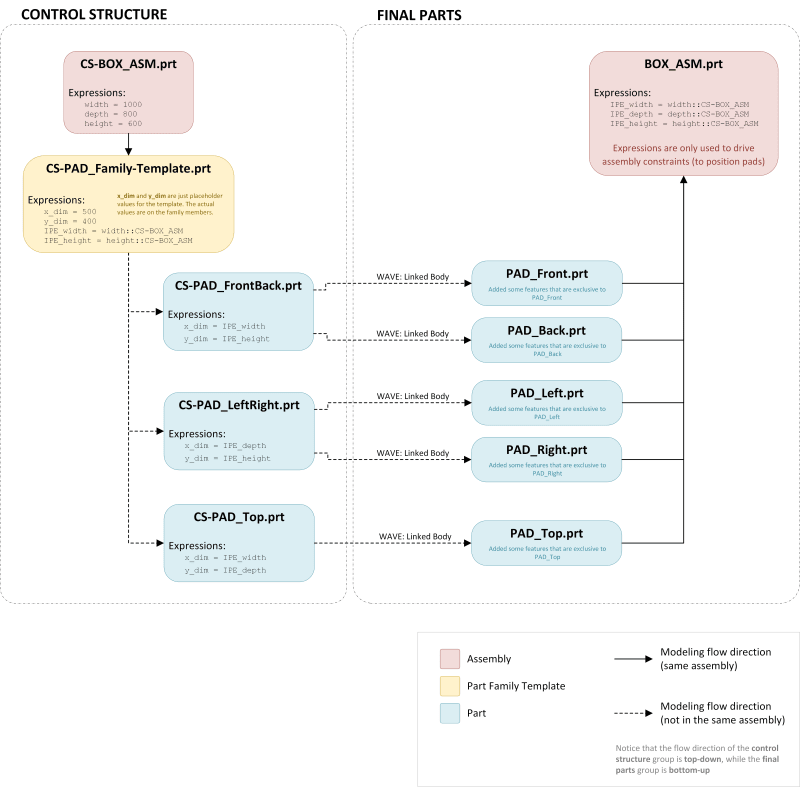
The "box" has 5 sub-assemblies called "pads": front, left side, right side, back and top pads. The problem is that the boxes are not standard, they're all custom-made depending on customer needs (the only thing that changes is the overall size), so it changes on every order.

So, lets say we have a custom order for a 0.6 X 1.0 X 0.8 m (width X depth X height) box. Front and back pads will be 0.6 X 0.8, both sides will be 1.0 X 0.8 and the top pad will be 0.6 X 1.0. All of the pads are modeled the same, same thicknesses, same bends, same holes and detailing features, except for the overall dimension. The acoustic foam should follow the dimensions of each pad.

I'd like to input only 3 values: width, depth and height of the box, and have NX to update everything. Also, I want to make only one model for the pads, in a way that if I change one of them (adding a new hole or changing a bend, for example), all of the other pads update as well. At the same time, the pads have to be different in size.

What would be your approach on that?
I though of part families, but couldn't figure out how to make it work for this specific case, also I read that part families should be used only for standard parts that don't usually change and that it is not recommended to nest part families.

Thanks!
 
Replies continue below

Recommended for you

This is, without the license for Product Template Studio ( PTS) a typical case for a "Reusable component" ;
A Reusable component will let you change all the required variables "width, depth and height of the box," and when this is done, it has an option to clone this into new files.
I suppose you save this order/ the output items?
What NX version is this ?

The PTS can add a very nice User interface on top of parametric assemblies but this application you describe should not need that.

I can link some relevant document tomorrow.

Regards,
Tomas


Never try to teach a pig to sing. I wastes your time and it annoys the pig.:)
 
Toost,

I'm using NX 1980 and I don't have PTS.

When you say Reusable component, you mean the Reusable Objects explained under the "Reuse Library" in NX's help docs?

As outputs, we just save the DXF for laser cutting, a STEP file for future reference (if needed) and some drawings exported as PDF files. We don't usually save the NX files. What I'd like to accomplish is: open assembly > change width, depth and height > auto-update everything > export DXFs and drawings > close without saving changes.

Relevant documents would be a great help, thanks!

I feel like this is such a common situation, isn't there an easier way to accomplish this? I feel like it should be possible with a combination of part families and/or control structures (parts used only to drive other parts through WAVE linking).
 
I tried a somewhat dirty solution, but it seems I'm doing something that I shouldn't.

[tt][ol 1]
[li]Created a "control structure" part ("cs.prt") that defines 3 expressions: width, depth and height[/li]
[li]Created a "control structure" part family ("cs-pad template.prt") for the pads[/li]
[li]Created interpart expressions in "cs-pad template.prt":[/li]
[ul]
[li]IPE_width = cs::width[/li]
[li]IPE_depth = cs::depth[/li]
[li]IPE_height = cs::height[/li]
[/ul]
[li]Modeled the "cs-pad template", it has two principal dimensions: "x_dim" and "y_dim" which define its size.[/li]
[li]Added 5 family members:[/li]
[ul]
[li]"cs-pad_front" and "cs-pad_back" . -> x_dim = IPE_width | "y_dim" = IPE_height[/li]
[li]"cs-pad_left" and "cs-pad_right" . -> x_dim = IPE_depth | "y_dim" = IPE_height[/li]
[li]"cs-pad_top" . . . . . . . . . . . -> x_dim = IPE_width | "y_dim" = IPE_depth[/li]
[/ul]
[li]Created the final parts "pad front", "pad back", "pad left", "pad right", "pad top"[/li]
[li]In each of the final parts, created a "Linked Body" (through WAVE Geometry Linker) feature to the respective family members. For example: "pad front" has a "Linked Body" feature linking it to "cs-pad_front" body. They're not in the same assembly, they're separated parts[/li]
[li]Added some holes and detailing features that are exclusive to each of them ("pad_front", for example, has 4 holes, while "pad_back" has only 2 in different positions)[/li]
[li]Assembled everything in "acoustic_box_asm.prt"[/li]
[/ol][/tt]

That way, I can only open "cs.prt" and "acoustic_box_asm.prt" and change the 3 key expressions in "cs.prt".
It seems too complicated for a simple task and updating it is slow. Can someone enlighten me?
 
We do the same thing with a standard design assembly of moderate complexity that is repeated with infinite variations. It takes a while to rebuild but compared to modifying everything by hand is fast. Cloning the assembly for a design must include ALL of the necessary files or the inter-part expressions point to the wrong file. PTS is an extra license and only really provides a neat interface to the part family feature (only from observation, not from use), and seems to have the same limitations.

The method you are using is much more flexible.

NX 1899 Windows 10
 
I would say the described method is slightly overworked relative the described outputs.
I would have created a small assembly like the below:

Assy
|-top​
|-left​
|-right​
|-front​
|-back​

In the "assy" I create the three expressions :
Height=500 ( numbers here are examples only since I do not know the sizes you work with.
Depth=400
Width=300

In each of the component files such as the "front" I link the expression "p22" :
"p22=assy::height" ( i.e the local expression "p22" will read the file "assy" and the expression "height".)

If your session isn't "delay interpart updates" everything will update as soon as you change the expression in the "assy".
If you add this assy to the "reuse library", you can easily configure a little dialog where one enters these expressions and it can include an image illustration.
And this reuse assy can use a external spreadsheet for "pull down values" of the height width etc.
This dialog will include an clone option in case you would like so save the structure for later references.
( the NX "Clone" will remap inter part expressions which "save as" does not)

Side Note, NX can do either "inter part expressions " and "overriding interpart expressions"
An "overriding..." will force the value of an expression in a different part to have the value forced, the component does not have any expressions setup, the assembly forces the components to have new values.
Regular interpart expressions "reads the value in a different part" in the example above the components are reading the values in the assembly. Not overriding.

Regards,
Tomas


Never try to teach a pig to sing. I wastes your time and it annoys the pig.:)
 
Toost,

Although your suggestion is simpler, unfortunately it doesn't totally comply to my needs ("I want to make only one model for the pads, in a way that if I change one of them (adding a new hole or changing a bend, for example), all of the other pads update as well. At the same time, the pads have to be different in size.")

The way you described is, of course, the most straightforward way, but if I understood it correctly, each pad is independent of each other (if I, for example, add a hole in one of them, the others won't replicate).
 
Without an illustration , it's difficult to get the "total picture".
Where did you find the method of using a "Control Structure" ?
It's a concept that i would say is like "shooting mosquitos with anti aircraft cannons" for this purpose.
The NX Part families is a tool that is brilliant in producing variants of parts ( different sizes such as fasteners ), but it's limited in that it does not allow you to add features to an existing part family member. - You can load a PF member and add say holes to it but you cannot save it.
The reason is that if you update the family members from the template, NX will simply replace the member file on disk and your holes will be no more.
at the same time, it sounds as if this is a feature you have used, you add features to the template and update / NX creates new members containing the added features.
Reusable components are in that aspect more forgiving, you can after adding the holes etc still edit the reusable component with the defining dialog, and added features will stay.

You mention you do Wave links, you can do this and use the the time stamp option , lock the link to always be after any added features in the master, that way any new features added in the master body will appear in the linked bodies, and any features added to the linked bodies will stay after the link feature.
Notice that wave links are not restricted in "direction", you can link in any direction in the assembly structure. The master can be in the assembly as well as in any component and the "receiver" can be anywhere. - There is a licensing restriction in that both master and slave must both be in a common assembly to "be alive". ( else you need the Wave engineering license)
In your example the master slave can be in the control structure while the only the slaves exist in the final parts.
In my example, the "front" component can be the master and the others are slaves.


Regards,
Tomas

Never try to teach a pig to sing. I wastes your time and it annoys the pig.:)
 
Toost,
thanks for the suggestions. I'm doing something similiar as your second suggestion.

I found the method of using Control Structures in Siemens Help Docs. Link: Control Structure. (At Siemens Help Docs > Browse NX help by product area > Assemblies > Interpart Modeling > WAVE > Control Structure)

All of that is well documented (create a control structure assembly with all driving expressions and "seed" geometry > create a new assembly with final parts > use "Linked Body" and interpart expressions to model the final parts).

My only question is how to include Part Families in that workflow. I'm uploading a picture of what I tried:
ESTRUTURA_DE_CONTROLE_kfonxz.png


It seems cumbersome and I can't get it to update properly. Seems too complicated. Notice that the part family members are not in the same control structure assembly (actually, the family members are not inside any assembly, they're just isolated parts).
I wonder if the problem is that I'm linking family members to the final parts. Isn't that supported (due to they being read-only or something like that)?

Doing the same thing, but without part families, works fine. But in that case I'd loose the ability to change just one part (the part family template) if I want to replicate the changes in all of the pads.

The way I want it to work is: if I want to make a change in all of the pads (like adding mounting holes, lightening cutouts, adding or changing bends etc), I can just edit the part family template (CS-PAD_Family-Template.prt), then the part family members would auto-update and, finally, update the final parts. If I want to make changes exclusive to each of the pads (like adding a small cutout with our brand logo only in the front pad, or add some mounting holes that are exclusive to the top pad), I could edit only the final parts (PAD_Front.prt, PAD_Top.prt...).

Is there a better way to do that? Would Product Template Studio or Reusable Components solve that problem in a simpler way?

Edit: added the image file as a PDF attachment for better resolution.
Control Structure PDF
 
Did you try the "promote body" over the partfamilies?

Gelson Z. Nicoletto
Eng. Supervisor
Mould Design
Brazil
 
Status
Not open for further replies.

Part and Inventory Search

Sponsor