Continue to Site

Eng-Tips is the largest engineering community on the Internet

Intelligent Work Forums for Engineering Professionals

  • Congratulations IDS on being selected by the Eng-Tips community for having the most helpful posts in the forums last week. Way to Go!

Best detail for pinning steel rafter to concrete panel?

Status
Not open for further replies.

Tomfh

Structural
Feb 27, 2005
3,485
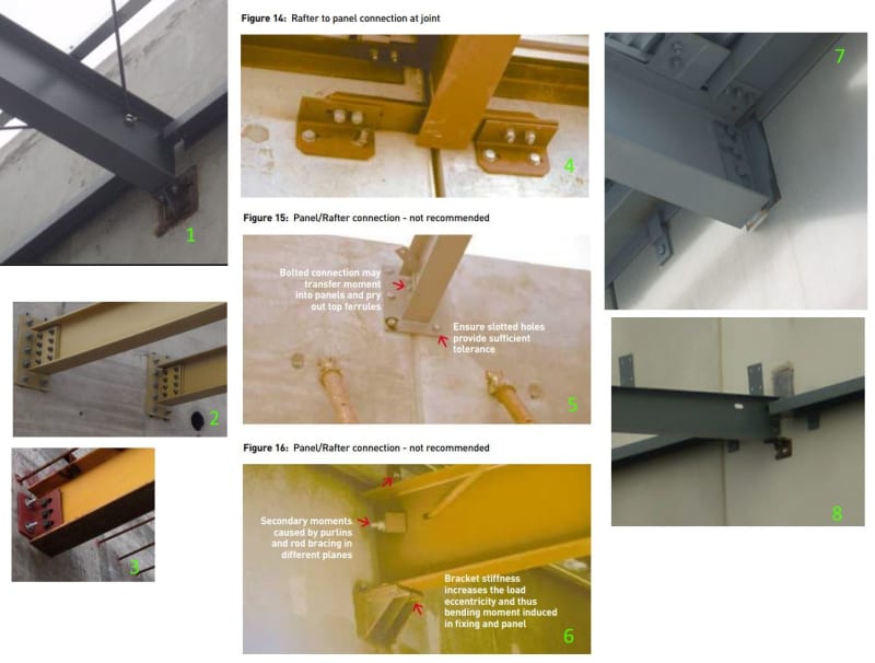
What is your preferred detail for pinning a steel rafter to a concrete panel?

Here are some details I grabbed from the web, to aid discussion.

panel_connections_mqn0qp.jpg


Some considerations:

A. Cast in weld plates vs. anchors?
B. Flexibility requirements? How to assess the anchor tension?
C. Seat vs web support?
D. Detail at joints vs Detail clear of joints?
E. Consideration of rafter size on connection choice?
 
Replies continue below

Recommended for you

I like 1,6 and 7

A. I think both can work, however I do like to have at least 1 cast in plate per panel. I prefer expansion, casting or screw anchors with chemical coming last for rafter connection.

B. I find this depends on panel reo.

C. Either, they both have an eccentric load that needs to be accounted for.

D. Prefer clear of joints, edge distances seem to be increased with every new test of an anchor.

E.yes/load and also fixity requirements.
 
#7 Is the most common for us. #3 is a common repair detail if/when things are missed. I wish people would spec #4 since I dislike dealing with embed plates at joints very much, but it is exceedingly uncommon given the extra detailing/steel. From the erector standpoint I suspect many would like the Meadow Burke (Leviat) rapid lock connector, but it is not common in my neck of the world. Link Halfen and Piekko also have many shear connections that avoid welding as well, but some come from other countries and delivery is a problem.
 
#7 is my favorite overall.

#1 is my second favorite and, I imagine, probably does the best job of actually being a pin for the heavier connections. #8 looks even more "pinny" owing to the absence of the cleat stiffeners but probably only works for fairly light loads.

#2 looks to me to be a way to call the connection plate a flexural extension of the beam so that eccentricities can be ignored in a high demand connecting. It a clever approach to be used in hail Mary situations.

In connections that would have multiple rows of fasteners perpendicular to the shear, post installed anchors drive me nuts. The requirement here to consider all of the load delivered to the front row of anchors tanks a lot of reasonable seeming configurations in my experience.
 
7s my 'go to'. I should have added... my favourite for CIP, too. I prefer not to do post applied fasteners with precast.

Rather than think climate change and the corona virus as science, think of it as the wrath of God. Feel any better?

-Dik
 
So I recently spec'd a proprietary embed called EM-BOLT, which may become my new favorite depending on how construction goes... we shall see.
 
bones, what is the construction tolerance for the EM-Bolt? Halfen makes an insert that is very efficient for bolting along the same lines, but must be set very accurately.
 
I believe they use oversized holes on one leg of the connection angle for up/down and side-to-side adjustment, and long slotted holes on the other leg for in-and-out adjustment. Simple but clever.

EMBOLT_Impact-Drill_jrsu1r.jpg
 
Bones,

That type arrangement give good tolerances to assist erection, but if all those bolts are tightened, the connection can transfer moment to the panel, and it doesn't take much to initiate cracking. That's why a single horizontal line of bolts into the panel is preferable, similar to detail 4, but not necessarily at a joint. Joints are best avoided.
 
I see what you are saying Hokie. In reality, all shear connections create prying forces in the connection, right? The EM-BOLT inventor did post a report on their website of full-scale testing performed at the University of Maine. The testing was done with the plates installed at the top of a panel.

In the case of my project, they are doing a full custom delegated design of these embeds with supporting calcs provided, so I can check how they handle this issue. I've seen some cases where they will use long, deformed bar anchors with 90 degree bends for the top anchors near the top of a wall.
 
Thanks bones. I would be interested for a report how these go if you use them. We rarely have final shop dwgs when it is time to do our precast shops, so embed plates are oversized 2" beyond the beam in each direction. I did not see a lot of room for adjustability on the EM-bolt drawings, and the dwgs are not overly clear who supplies the connecting clip. The embed itself has no more adjustment than any other steel elements. Adjustment is very important. Errors mean fixes to me, and that wastes my time. Many precasters work to the nearest 1/4" and steel guys can be less than 1/16" with their level of automation. There is not a lot of inventing going on with those. The inserts they use in the panel look like standard Dayton Superior parts.

I bet they are relying upon the slots to relieve the bending forces. They do have a complete test on their site, but I did not delve into it.

Images from their CAD file:
image_im9clp.jpg

image2_parpyw.jpg


Piekko has a smart hidden connection for large precast beams. Here you can see grooves that allow vertical and lateral adjustment in the field.
Piekko_PCS_p5ksds.jpg
 
That detail shows slotted holes on both legs on the connecting angle. So the only adjustment lacking appears to be in the vertical direction. I will be sure to report back on how my trial project goes.
 
bones,
Yes, all connections create prying forces, but with a single horizontal row, not much.
 
Brad805

"I bet they are relying upon the slots to relieve the bending forces"

Yes I would like to know whether the slots are there to relieve the bending on the panel.

If they are there for that reason and if bolts are only snug tight then there would be little moment transfer to the panel regardless of the number of bolts connecting the plate to the panel. The connection would be an improvement to 7 which is my preferred connection for tilt ups.

 
rowingengineer said:
I like 1,6 and 7


Brad said:
#7 Is the most common for us.

Kootk said:
#7 is my favorite overall.

dik said:
7s my 'go to'


Two Questions for you guys regarding #7:

1. What sort of plate anchoring detail do you use? What sort of attached studs and/or reinforcement?

2. How do you assess moment due to connection rigidity? Is #7 (with slotted holes) sufficiently flexible that you can design as a simple support? Or should you be assessing as rigid (or semi rigid) when assessing anchor bolt tension force?


Hokie66 said:
That's why a single horizontal line of bolts into the panel is preferable, similar to detail 4

A lot of the places in Australia (eg Bunnings) seem to rely on this detail. I quite like it, but it's not one of our standard details. The single horizontal bolt line and torsional flexibility of the angles seems a good way to minimise unwanted prying. Are there downsides to this concept that you're aware of?
 
(I don't do these buildings)

What are the issues with 3? Looks simple enough -just risk off hitting reo?

Is 7 site welded with ordinary paint repair?
 
1. I use the u-bar standard plate with extra N12 bars base on the testing from RJB
castin_uc69br.png


2. I model it in FEA, and check the ecc forces for all elements, and then do the same for the tilt panels.

3. The detail over the joint is a nice detail to reduce ecc, however I find on most of my projects it isn't possible to get panel joint and rafter alignments. In my modeling teh reduction in ecc force isn't as great as one would think.
 
Rowing said:
2. I model it in FEA, and check the ecc forces for all elements, and then do the same for the tilt panels.

How do you assess continuity and resultant negative moment? How to ensure the U-bars don’t pull out?
 
Sorry assess continuity? Can you explain a bit more?

If you mean what moment is transferred from the beam to panel, that is what fea will give you, the moment you need to work with and the restraints/spring supports for your 3d model including ecc.

As for U bar pull out the rjb testing is fairly detailed, the results are enough for you to be able to design this connection.
 
Status
Not open for further replies.

Part and Inventory Search

Sponsor