Continue to Site

Eng-Tips is the largest engineering community on the Internet

Intelligent Work Forums for Engineering Professionals

  • Congratulations KootK on being selected by the Eng-Tips community for having the most helpful posts in the forums last week. Way to Go!

Best steel column-beam-brace joint to the column weak axis (web direction) ?? 2

Status
Not open for further replies.

Abdelrahman_Yousef

Structural
Jan 19, 2019
9
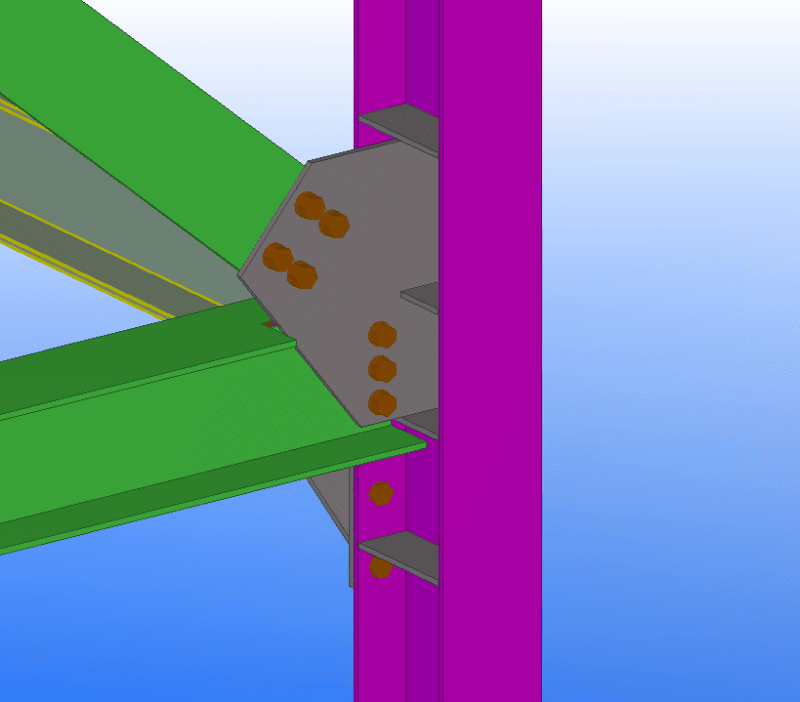
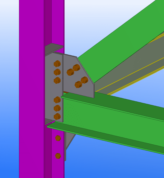
As the subjects suggests , this joint has been giving me headaches.
In the direction of the column main axis, I have a moment connected main beam and I need the back transverse stiffeners in the column.
How do I connect the strut and brace in the other direction while maintaining erect-ability of course .

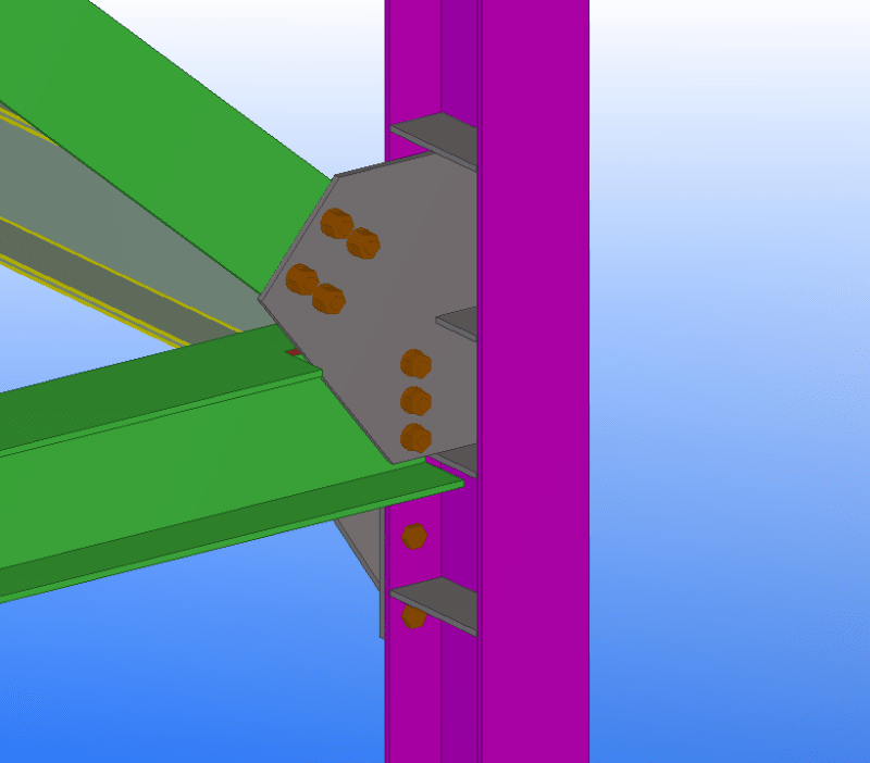
I've seen the following 2 samples connections before, so can anyone give me advantages and disadvantages of each ?
what checks may be critical that might pass me by ?
or if there are any other suggested shapes.

1111_rttvhl.png


2222_hvgixi.png
 
Replies continue below

Recommended for you

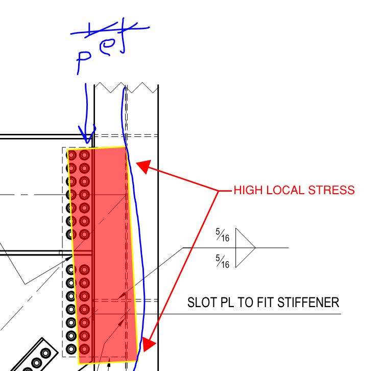
I think they mean the horizontal load from the top bolt Group causing bending in the cover plate in UFM speak.
 
Agent666 said:
I think they mean the horizontal load from the top bolt Group causing bending in the cover plate in UFM speak.

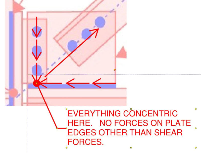
I'm starting to feel foolish for not getting this. Why would there be such a horizontal force? I'm all concentric / mechanically perfect at is it were.

c02_a1tbbg.jpg
 
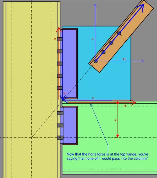
It's late and I'm doing actual work, but this is what I'm getting at. I'm not sure I buy that the horizontal load from the brace will completely bypass that joint - at least some portion of that H force will want to pull the column (I think).
image_elquqx.png
 
Mr. Koot,

The plate shared by the beam and gusset in my detail is designed solely for shear and axial. There were no moment connections (or moment loads) in my submission. I would use a different strategy (flange plates, end-plate, or maybe a beam-stub/splice) if I had to transfer moment loads. I did neglect to show the beam-to-column-flange moment connection the original poster showed.
 
DrZW said:
There were no moment connections (or moment loads) in my submission.

I was actually inquiring about something different and realize that your connection is not a moment connection. Rather, it seems to me that your vertical bolt groups on the beam and gusset must be transmitting moment to the knife plate. Otherwise, it would seem that the knife plate would be delivering a large moment to the column web as a result of the horizontal eccentricity between the web and the center of the vertical bolt lines, where the shear would be assumed to be delivered.

c01_j5fqg7.jpg
 
winelandv said:
I'm not sure I buy that the horizontal load from the brace will completely bypass that joint - at least some portion of that H force will want to pull the column (I think).

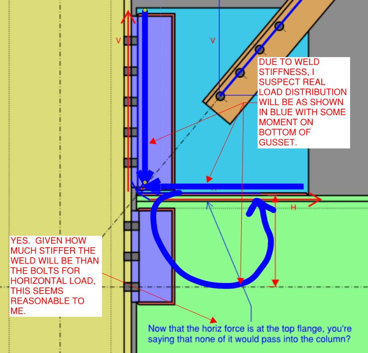
Any chance you've gotten so good at UFM that you now struggle to think in terms of the KISS method that preceded it? I still think that I'm good here but the conversation sort of bifurcates as follows:

1) What are allowable assumptions in connection design? Along with some other assumptions that we don't need to get into here, I believe that I'm allowed to assume any force distribution that satisfies equilibrium. And I believe that my model does that without horizontal brace load being transferred to the column. This is no different than UFM where the assumed distribution is not envisioned to be the "real" force distribution but, rather, a single force distribution of many that satisfies equilibrium and is chose for its calculation expediency and the compactness of the resulting connections. As shown below, I actually feel that my assumed force distribution is fairly consistent with natural stiffness principles which is always a good thing for obvious reasons.

2) What will the real connection stresses be? Who knows. As i said, I feel that my distribution does a pretty good job of reflecting the stiffness of the variable elements. That said, I'm sure that there will be some degree of horizontal force moving from the gusset into the column for any number of reasons:

- No doubt there will be some non-brace induced axial forces moving through the beam/column joint.

- The gravity and eccentric axial loads will rotate the beam end some and, in that sense, impose a moment on the connection to the column plate. And that will express itself as a distribution of flexurally induced horizontal force delivered to the column flange plate. Certainly, if plate welds to the column flange would be fragile with respect to minor horizontal load transfer, that is something that I'd want to address.


c01_q66qfx.jpg
 
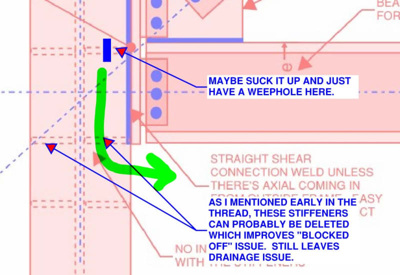
@skeletron: another thought with regard to the "blocked off" business. It really is an interesting point that I'd not considered thoroughly enough initially. You must have some fabricator experience I'm guessing.

c01_vtj6ns.jpg
 
This has turned into a very informative discussion.

Can someone give me any design guide/steps for this connection?
specially the effect of tension/comp. balance effect on gusset plate ?
how can I make sure it will not buckle or twist or any rupture would happen to it ?

image_zpsd8x.png
 
KootK said:
Any chance you've gotten so good at UFM that you now struggle to think in terms of the KISS method that preceded it?

No, definitely not that - more like, totally forgot to balance the horizontal brace load with the horizontal load that must be in the beam (i.e., a towards-the-column force). I work in a field of belts and suspenders, so saying to design the beam/shear tab/plate/column load path for shear and tension made sense to me, from a "designing for a worst-case load is faster than trying to prove out a lower load".

At any rate, putting the brace work point on the corner of the gusset certainly makes the connection design more straight forward than the standard UFM approach.


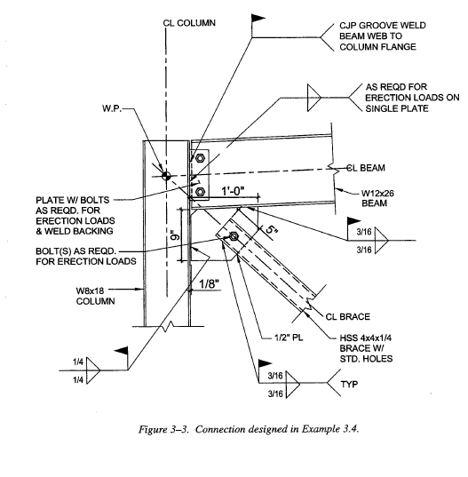
OP. Page 5-49 of the AISC Seismic Design Manual (3rd edition, corresponding to AISC Steel construction manual 15th Edition) contains a step-by-step example you can follow to complete your work. It frames to a column flange, but is similar enough for you to modify as needed. A similar example is given on page 3-25 of the 1st edition, corresponding to AISC SCM 13th Edition.
 
DrZoidberWoop said:
Page 5-49 of the AISC Seismic Design Manual (3rd edition, corresponding to AISC Steel construction manual 15th Edition) contains a step-by-step example you can follow to complete your work. It frames to a column flange, but is similar enough for you to modify as needed. A similar example is given on page 3-25 of the 1st edition, corresponding to AISC SCM 13th Edition.

do you mean this one ?
image_ibg4h1.png


It's not similar to the connection I'm asking about

KootK said:
That's a whole lot of question for a forum thread. You might need and entire book to reference: Tamboli

As a freebie/starter, try this:Whitmore Article

I generally want to know why it's not more used compared to UFM or KISS Joints ?
Is there a disadvantage that I'm not getting ?
 
If you're looking at the 3rd edition manual, that is on page 3-24. Look at the example on the next page. The brace is different, but the connection concept is the same. Either way, at this point, you have far more than enough information to complete the connection design.
 
@KootK:
I dipped offline for a bit. So I'll respond in general to support some ideas that were raised with the Q&A on my previous post.

COLUMN BLOCKING
I brought up this because it affects the "finishing" of the column: painting, galvanizing, fireproofing. In each of those three finishing scenarios, I just imagine that the blocking of that small portion of column by the flange plate would increase the complexity of the preparation of the column. You would have to paint the inside of the column before welding the flange plates, which means you would need to tape the weld locations off, move the column to the paint shop, paint it, move the column back to the main shop, attach the flange plates, then bring it back to the paint shop for painting of the flange plate section. Galvanizing would just inconvenience the dippers if that 1/2" hole that you were suggesting, got clogged. And it might be difficult to inspect that inner portion (although it would likely be protected given the mechanics of the galvanizing process). And I'm not sure how you would spray fireproofing in that little blocked off portion. It could potentially be contested as a weakness.

Again...I'm just trying to speculate on what this singular column may have to face. Obviously, there might be situations where the blocking would be okay. It's just food for thought.


FLANGE PLATE IDEA USING SEPARATE PLATES
The idea of having multiple smaller plates is a neat one. I do think it would work in terms of load transfer. You would need to get the fabricator on board, because having more small pieces can increase their workload.


WELDED COLUMN STUBS FOR PERPENDICULAR CONNECTIONS
Yeah. I thought about this suggestion. It's come up in a few recent threads. I like it now. Obviously making your columns into a christmas tree (with welded stubs) would need to be organized with the erector. Some like it (it can make lifting easier). Some don't like it (load imbalance in some cases). And you would need to make sure that the column + stubs can fit in a galvanizing tank or truck. But it's a great connection to reduce the bolt access requirements at the column web. Again...I'm trying to throw every scenario at this connection just to speculate.


Some great discussion in this thread. Brace-beam-column web connections are truly imperfect connections that you need to make concessions with the design in order to move forward. Truly a connection that will help bring the constructors and designers together to find a compromise.
 
Thanks for your contributions.

I have a question regarding extended plates,
If I'm a fabricator with connections design scope, EOR is giving me only a criteria for connections design (no Staad.Pro model), in that case who is responsible for checking column for eccentricity moment ?
That's considering I'm sending him my connections report for approval & I don't have sufficient data to check column for additional moment.
 
Status
Not open for further replies.

Part and Inventory Search

Sponsor