Hello,
I would like to start a discussion about the best way (mesh quality vs number of elements vs results accuracy) to mesh a large plate with a lot of small holes.
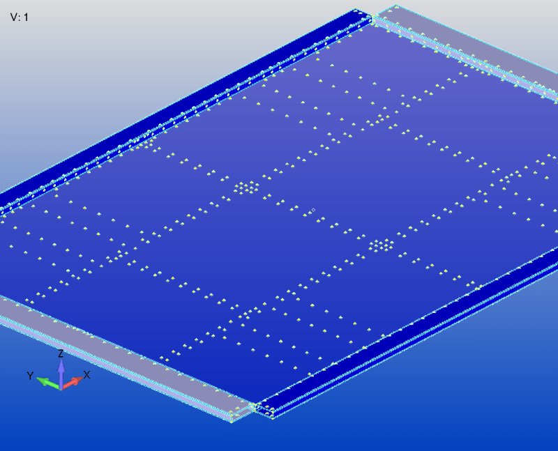
The thing is that I have a large plate (2000 [mm] x 1350 [mm]) which contains a lot of small holes (diameter 3.2 [mm], see image below).

If I use 10 [mm] elements in order to avoid having a small element size and thus, hundreds of thousands of elements, the mesh is really awful.
Even with 5 [mm] elements this happens and the amount of elements is considerably larger. Worth is mentioning that what I showed in the image is just a part of the model; therefore, I cannot put as many elements as I want.
So I said okay, I don't consider the holes, and then I take the position of the center of the holes and I create RBE3 + BEAM elements. The thing is that there is no API for doing it and it will take me a lot of time to do it, and I would have to use only beams to connect the elements, without the possibility of using a spider + beam representation of the fastener.
Worth is mentioning that the idea of using contact is not applicable in my model, I must represent the fasteners.
My question is then open to discussion, experience and suggestions : What is the best trade off in this case ? What would you do ?
Do you have / know any API for doing it ?
Thanks in advance !
Cordially,
EC
I would like to start a discussion about the best way (mesh quality vs number of elements vs results accuracy) to mesh a large plate with a lot of small holes.
The thing is that I have a large plate (2000 [mm] x 1350 [mm]) which contains a lot of small holes (diameter 3.2 [mm], see image below).

If I use 10 [mm] elements in order to avoid having a small element size and thus, hundreds of thousands of elements, the mesh is really awful.
Even with 5 [mm] elements this happens and the amount of elements is considerably larger. Worth is mentioning that what I showed in the image is just a part of the model; therefore, I cannot put as many elements as I want.
So I said okay, I don't consider the holes, and then I take the position of the center of the holes and I create RBE3 + BEAM elements. The thing is that there is no API for doing it and it will take me a lot of time to do it, and I would have to use only beams to connect the elements, without the possibility of using a spider + beam representation of the fastener.
Worth is mentioning that the idea of using contact is not applicable in my model, I must represent the fasteners.
My question is then open to discussion, experience and suggestions : What is the best trade off in this case ? What would you do ?
Do you have / know any API for doing it ?
Thanks in advance !
Cordially,
EC
