Eng-Tips is the largest engineering community on the Internet

Intelligent Work Forums for Engineering Professionals

  • Congratulations waross on being selected by the Tek-Tips community for having the most helpful posts in the forums last week. Way to Go!

Bevel cutting W-section steel beam at support 1

Status
Not open for further replies.

Montreal.eng.

Structural
Apr 3, 2022
11
0
0
CA
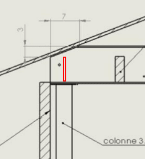
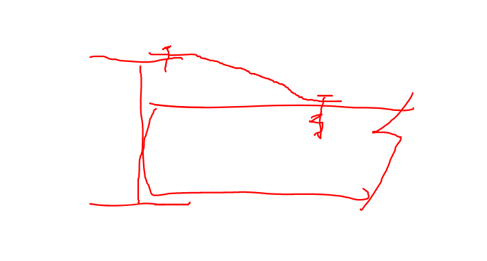
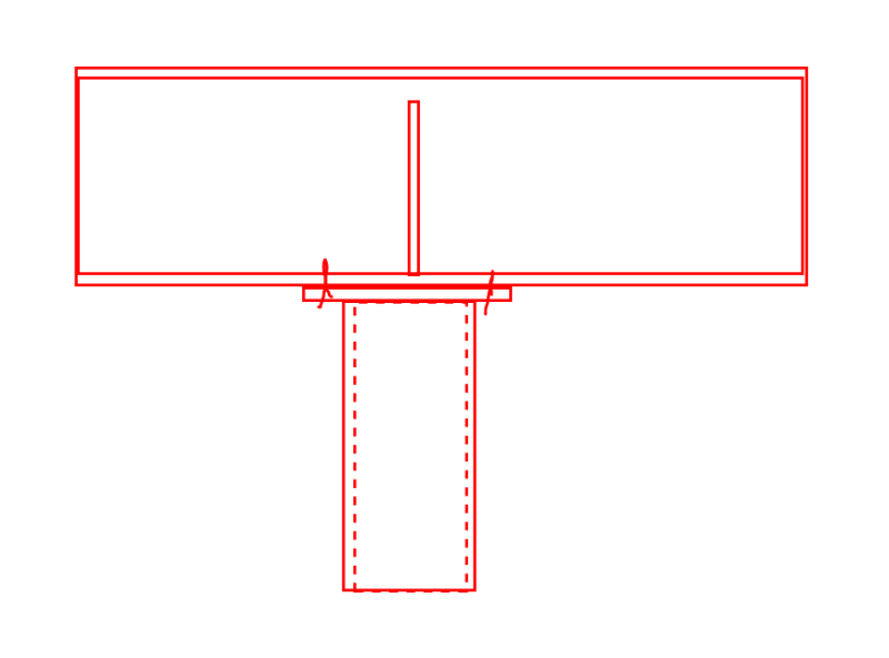
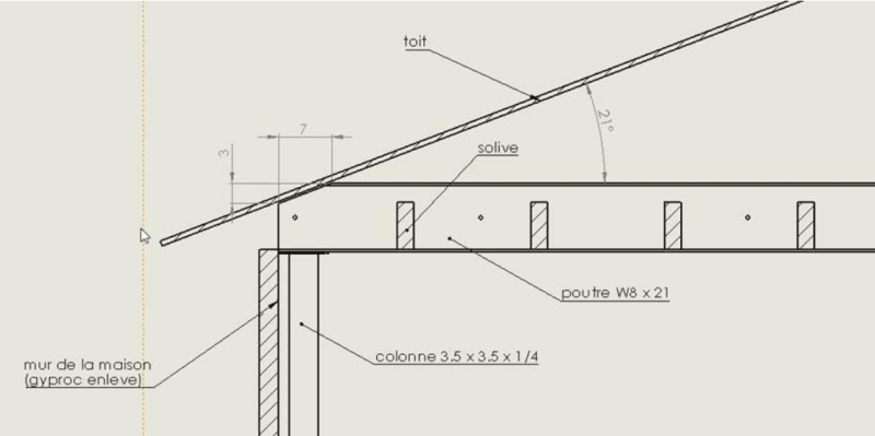
Hello, I have a customer that is asking if it's possible to bevel cut a steel beam in order for them to recess a W8x31 beam into their attic. In my opinion if the cut doesn't go beyond the support width it doesn't weaken the beam in shear nor in bearing. The load on the beam isn't immense, It carries some of the roof and attic load, the steel beam and columns was at the request of the client that works for a steel company.

I just want to make sure that I'm analysing this correctly.
Also, since the top of the beam will be popping into the attic, I will have to ensure top lateral bracing at supports. Do you guys have any efficient way to do this? Is a

The sketches below are written in french (If the name isn't obvious enough I'm from Montreal, Quebec)
Poutre = beam
colonne = column
Solive - Joist
Toit = Roof
Bevel_cut_czx4am.png


Thank you in advance,
 
Replies continue below

Recommended for you

1) I agree that this is possible one way or another.

2) I agree that neither shear nor or bearing should be any more critical than they would have been without the bevel cut.

3) I would want a partial height stiffener over the column for added rotational stability, even if it isn't required for web crippling/yielding.
 
OP said:
Also, since the top of the beam will be popping into the attic, I will have to ensure top lateral bracing at supports. Do you guys have any efficient way to do this?

Maybe a bent flat bar every fourth joist? I've seen similar things done with clip angles and shear wall hold down anchors. One tries to avoid interfering with the end slope of the joists but that is not always possible.

C01_zlxxeh.png
 
If your joists are tight fitting, and go most of the way to the top flange, what are peoples' thoughts on omitting dedicated flange bracing and considering the joists as bracing the flange via web bending?
 
KootK said:
I would want a partial height stiffener over the column for added rotational stability, even if it isn't required for web crippling/yielding.

I'd go for full height.

AISC 360-10 J.7. Unframed Ends of Beams and Girders said:
At unframed ends of beams and girders not otherwise restrained against rotation about their longitudinal axes, a pair of transverse stiffeners, extending the full depth of the web, shall be provided.

jayrod12 said:
If your joists are tight fitting, and go most of the way to the top flange, what are peoples' thoughts on omitting dedicated flange bracing and considering the joists as bracing the flange via web bending?

I wouldn't trust them to get it tight fitting - at least not tight enough to maintain stability of the beam in a high load circumstance. I prefer discreet connections in these circumstances. One option could be screwing (bolting if the flange is to thick) a nailer to the top flange for a short segment and using a Simpson VB knee brace. It's a modified off the shelf version of KootK's strap.
 
You want to leave a bit of a gap between the steel beam and the wood framing for shrinkage, etc.

Rather than think climate change and the corona virus as science, think of it as the wrath of God. Do you feel any better?

-Dik
 
Hypotheticall, beam webs packed full with wood bolted to web, joists well cut with flush framed hangers. Does that change your opinion?
 
jayrod12 said:
If your joists are tight fitting, and go most of the way to the top flange, what are peoples' thoughts on omitting dedicated flange bracing and considering the joists as bracing the flange via web bending?

I'd be fine with that up to a beam that would be [joist depth / 0.6]. Same as we do when it's a steel beam doing the bracing. This is actually what I was getting at when I mentioned the hold down anchor and clip options.
 
Thanks to everyone that answered, it helped clarify things alot. I think it will be simpler to have web stiffeners welded since the bevel cut will eliminate the flange at that extremity of the beam making a nailer with braces trickier to do.

Not related to the post: I recognize alot of the names of the people that answered from other threads and want to let you know that your implication in this forum and the time you spend sharing your knowledge is greatly appreciated especially with the greener engineers/EITs that are starting up and that don't always have a superior available to help. Thanks again.
 
phamENG said:
I'd go for full height.

I don't agree with your code references with respect to their requiring a full depth stiffener here:

1) I think that it's pretty clear that clause is speaking to the grabbing of the top flange for twist restraint. Here, the top flange simply isn't available to be grabbed unless:

a) The stiffener is moved off of the column. This seems imprudent.

b) The stiffener slopes to the top flange. This seems extreme for the situation.

2) Virtually all of the beam bracing options discussed thus far do, in fact, restrain beam rotation about the longitudinal axis.

3) I'm not sure that we're even "unframed" here. There will be a cap plate and bolts, right?

AISC 360-10 J.7. Unframed Ends of Beams and Girders said:
At unframed ends of beams and girders not otherwise restrained against rotation about their longitudinal axes, a pair of transverse stiffeners, extending the full depth of the web, shall be provided.
 
1) I'd take it to the full available height at the column location.

2) But not at bearing, which I think is important.

3) Unframed end is defined as: "The end of a member not restrained against rotation by stiffeners or connection elements." I once had to write a report (under the "supervision" of my boss) for use in a court proceeding defending another engineer who made a mess of a large custom home. One issue was a steel beam supporting an unbalanced load - joists spanning something like 15 or 20 feet on one side and 5 feet on the other over a pretty long span. The beam was stressed to the max in flexure and barely met minimum deflection. The connecting elements all passed fine, but even so the beam was bent sideways at the support. It was relying on web bending to resolve the torsion, and it wasn't up to the task. The bottom flange, cap plate, bolts, and column were still nicely aligned. I took that early lesson to heart and have blindly followed J.7 ever since.
 
KootK,

My mentor at my first job instructed me to add the full depth stiffeners explicitly at the "beam on top of a column". He took "unframed" to mean beams framing in. Also, since the stiffener req is for beams "not otherwise restrained against about their longitudinal axis", it seems easier to slap the stiffeners in than to try and argue that there's enough torsional restraint inherent in the WF combined with the column to create the longitudinal axis restraint. A large factor in my reluctance to even attempt the argument is the lack of strength/stiffness reqs.

Of course, this is where you pull out a paper from [some person] examining this exact situation back in 198X, that showed for beams with a bf/d ratio of R, you don't need the stiffeners.
 
I'd check the beam as a coped beam (3" cope, 7" length) to get the approximate capacity at the end. My rough calc is saying something like 40-50% of the non-coped section's shear capacity and dominated by flexural yielding of the web. If you are using steel in a residential context (20ft span, 16ft trib), in the land of 50psf snow load, you might actually come close to this reduced capacity...

I would also ask the fabricator's preference on the bevel cut as shown. There may be complications with getting through the "k" distance at an angle. Strictly speaking, you'd want to radius any corners to prevent stress risers.

Lastly, I would be drawn towards using a horizontal stiffener across the web at the coped section and the vertical stiffener over the column. This is following some of the findings from Cheng's test through the 80s and then the 2001 paper "The Local Web Buckling Strength of Stiffened Coped Steel-I beam".

...I'm coming from an industrial steel background, so I'm also use to blowing things out of the water just to make it work en masse. YMMV.

 
phamENG said:
1) I'd take it to the full available height at the column location.

I would too. That's actually what I intended. That said, I wouldn't be fooling myself about that setup being "full depth" in the sense that J.7 means it.

phamENG said:
2) But not at bearing, which I think is important.

I disagree. If it makes you feel better, think of it as a short, unbraced cantilever from the first torsional restraint back to the column. Yeah, I'd rather have twist restraint at the support too, just as I would at a cantilever tip. But that is not always necessary and not always practical.

winelandv said:
Also, since the stiffener req is for beams "not otherwise restrained against about their longitudinal axis"...

Our beam is going to be restrained against rotation about its longitudinal axis. Several times along it's length by the sound of it.
 
@phamENG / winelandv,

Just to be clear, when I say "partial depth", that does not mean 1/4 depth. Rather, it means pretty much full depth but stopped short to make the fitting of the stiffeners more economical. As far as I know, the connection shown below is quite common for modern Gerber systems where it is deemed to be adequate for rollover concerns. That, or it's two stiffener cousin.

C01_xz3me3.png
 
Hmmm... since J10.7 states "At unframed ends of beams...." I had assumed that the whole section was talking about whether that unframed end is (somehow) "otherwise restrained against rotation". KootK, you're reading that say that if the beam is restrained against rotation at any point along the beam about its longitudinal axis, then no stiffeners are needed.

I've never thought of it that way, so bear with me as I poke at this. Say we've got a 20' beam with smaller beams framing in every 2.5' along the entire length, beam ends are unframed and sitting on top of HSS columns. I can see how this situation could meet the intent of J10.7.

What if the same beam/column setup, but a single beam framing in at the center? What if the same setup, but a single beam framing in 2.5' from one end only? Now I'm not so sure.

I'm not saying your wrong, I've just never thought of it this way before.
 
Status
Not open for further replies.
Back
Top