Continue to Site

Eng-Tips is the largest engineering community on the Internet

Intelligent Work Forums for Engineering Professionals

  • Congratulations IDS on being selected by the Eng-Tips community for having the most helpful posts in the forums last week. Way to Go!

Biaxial stresses in concrete beams 1

Status
Not open for further replies.

struct_eeyore

Structural
Feb 21, 2017
260
Hi all,

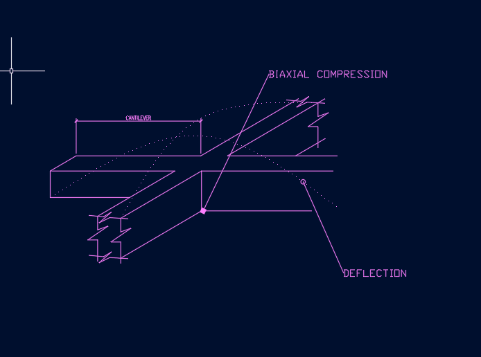
I have a case where one concrete beam supports another, a cantilever. The cantilever is perpendicular and runs thru the main beam. I've done this many times, but I've now started to wonder if there is some sort of stress check that need to be done for the biaxial stress that occurs at the shared prism of concrete at the intersection, esp. when beams are designed to capacity. In particular, for the case where the main beam is continuous, so that compression-compression case occurs. Any thoughts?
 
Replies continue below

Recommended for you

As far as I know you need the check the main beam for torsion. The moment in the cantilever will induce torsion in the main beam.

Interested to hear what other people say to learn about this matter.
 
To clarify, my cantilever has a backspan that is locked in at the far end. Torsion will not be a concern.
 
sketch_gb2bt4.png
 
I've done this many times, but I've now started to wonder if there is some sort of stress check that need to be done for the biaxial stress that occurs at the shared prism of concrete at the intersection, esp. when beams are designed to capacity.

I'm not 100% sure I follow your sketch (or the situation).....but you might could check the intersection as a (column-beam) joint as per ACI's provisions. I'd doubt you would have a issue though.
 
1) The cantilever beam will induce some torsion but it will probably be the compatibility kind and not a problem unless close to a torsionally stiff support etc.

2) If both cant and girder have compression at the bottom at the crossing joints, that might actually be a benefit as you'd get a bi-axial state of compression which we generally like.

3) If the cant induces tension at the top while the girder simultaneously is induces compression, I could see this being an issue actually. That said, I've see lots of these two and never seen anyone do a condition specific check for this.

4) This somewhat resembles the strut and tie case where a tie crosses your node and thereby you take a reduction in the allowable compression. I suppose you might do something similar here.

Neat

HELP! I'd like your help with a thread that I was forced to move to the business issues section where it will surely be seen by next to nobody that matters to me:
 
My thoughts were to check it on a Mohrs circle for max shear/principal stresses. What kind of values should be assigned to limit states in this case?
 
structee said:
What kind of values should be assigned to limit states in this case?

I don't recall where I've seen it but my understanding is that you get an increase in allowable compression stress of about 25%. Concrete compression failures are really tension failures in a way. High compression stress leads to high transverse tension stress as a result of Poisson ratio stuff. And that leads to a tensile splitting apart of the concrete perpendicular to the compression field. When a biaxial compression field is introduced, that tends to restrain the Poisson splitting and improves matters. Truly, if you have an issue here at all, I'd be looking a stress states that are compression in one member and tension in the other.

HELP! I'd like your help with a thread that I was forced to move to the business issues section where it will surely be seen by next to nobody that matters to me:
 
My 2 cents worth:-

3) If the cant induces tension at the top while the girder simultaneously is induces compression, I could see this being an issue actually. That said, I've see lots of these two and never seen anyone do a condition specific check for this.

This was the scenario I was primarily envisaging occurring based on the sketch. I have also never seen anyone do a check on this beyond ensuring you have the required 'hanger' reinforcement to support the load being transferred between beams. My view is sort of the opposite in that I don't see this scenario as an issue in practice, for example consider the following:-

If you consider a beam, on the tension face yes there is some tension in the concrete but in practice it cracks to the neutral axis in theory with minimal tension between the cracks. So in effect if you add in the cantilever compression transversely into the bottom of the beam you only have the transverse compression block going through this concrete with minimal tension transversely even though it's in the tension zone. In effect not really much difference to considering the isolated compression face of a beam in isolation. In my mind you have similar scenario, and simply adding compression transverse to this doesn't matter or certainly doesn't result in any measurable increase/decrease of capacity of the concrete in compression which might be going on in the zone where the two members overlap. In fact because the compression width increases through the supporting beam thickness the compressive stresses can spread along the beam some distance as well in the cross-over region of the two beams which may help.

I do agree that confined concrete will be able to resist a higher compressive stress, so in the case with both cantilever and supporting beam having compression coinciding then there may be some increase, but for practical design you're not going to gain anything by considering it because just past the crossover you are into a more critical case with uniaxial compression without any benefit to confinement from a confining compressive force acting transversely.

kootk said:
This somewhat resembles the strut and tie case where a tie crosses your node and thereby you take a reduction in the allowable compression. I suppose you might do something similar here.
I initially thought the same regarding strut and tie must have some allowance for this, so went off and looked at my local concrete design standard and couldn't find anything related to this. Care to link to the relevant provision in say ACI that discusses this. According to NZS3101 (NZ concrete standard) you can simply cross struts and ties without any reduction as far as I can tell. I believe this is because the overarching assumption is that the reinforcement provided for the tie takes the tension and concrete carries the compression and as such the forces are in different materials at the crossover point. Provided there is no deviation of the forces there is no nodal zone, hence no need to evaluate nodal stresses?
 
Agent666 said:
Care to link to the relevant provision in say ACI that discusses this.

You bet. You can't have tensile strain in the ties at a node without also having some degree of tensile strain in the concrete strut(s). And that's kinda like giving Poisson a Red Bull.

I'm unable to cite a source but I've always been under the impression that ties crossing struts anywhere other than at nodes is indicative of a poorly chosen STM.

c01_cufnhv.jpg


HELP! I'd like your help with a thread that I was forced to move to the business issues section where it will surely be seen by next to nobody that matters to me:
 
Yeah we have that too, my thoughts were that since the tension force from the supporting beam isn't changing across the nodal zone created by the cantilever compression, the transverse tie from the supporting beam simply passes through the node/strut. So clause 23.2.5 kind of comes into play.

That table is based on anchoring ties (i.e. vertical stirrups in the case of the cantilever beam (EDIT) in compression zone), not passing a tie through the nodal zone transversely in this case with effectively limited/no change in the bar force (in reality of course it changes slightly over the width of the beam it crosses depending on the change in moment, but for arguments sake lets say its more or less constant to illustrate the point I'm fundamentally trying to get at).

5_nvro0z.png


Edit: - was going to say as well, strut and tie in 2D, infinitely easier than 3D. Very little guidance on these types of complications in 3D models in codes or elsewhere that I'm aware of at least.
 
Agent said:
my thoughts were that since the tension force from the supporting beam isn't changing across the nodal zone created by the cantilever compression, the transverse tie from the supporting beam simply passes through the node/strut.

What is informing your opinion that the issue to watch is whether or not the force in the tie is changing? In my mind, tensile strain is tensile strain whether it's varying spatially or not. And tensile strain across a compression field is going to be a detriment to that compression field.

While ties may be code permitted to cross other struts, I still feel that should be avoided whenever possible as part of considered modelling. That, applying the same logic as at the nodes: induced tensile strain component normal to struts doesn't do those struts any favors. Sometimes it's unavoidable however.

HELP! I'd like your help with a thread that I was forced to move to the business issues section where it will surely be seen by next to nobody that matters to me:
 
What is informing your opinion that the issue to watch is whether or not the force in the tie is changing?
If its not changing and the force is in the reinforcement, then you aren't anchoring anything which I thought was your justification for applying the reduction factors (i.e. Nodal zone anchoring ## ties is what is noted in the table after all).

Combined with the concrete itself cracking to alleviate the concrete being in tension more or less means most of the tension force is in the reinforcement remote from the cracks, and at the cracks all of it is in the reinforcement. Lets say concrete never cracked ever and carried the force even in conjunction with some tension reinforcement. Then I'm more in your camp thinking the same things as you as its more like a 3D stress state in the concrete and you're looking at principal stresses more or less. But at the ultimate limit state most things will actually crack (in this case the tensile zones of both cantilever and supporting beam), and this conveniently gets you closer to the state somewhere out in the beam span as far as developing meaningful transverse tension stresses on your effectively '2D' nodal zones as the beams cross. Design stress states are after all a very coarse approximation for all the funky stress states going on in the concrete.

I know ties crossing struts isn't exactly the same as passing a tie transversely through the nodal zone, but I was looking for common ground as a way of explaining the OP's particular dilemma. I'm basically stating is it really an issue, because at least in my mind I've explained it away to myself as a non-event in terms of things to worry about in practical design. I'd be interested if anyone has anything that explains otherwise for future reference.

I still feel that should be avoided whenever possible as part of considered modelling
Agree. Just saying code allows for better or worse without any penalty applied at the point of crossing.
 
Agent666 said:
If its not changing and the force is in the reinforcement, then you aren't anchoring anything which I thought was your justification for applying the reduction factors (i.e. Nodal zone anchoring ## ties is what is noted in the table after all).

You're reading too much into that. Firstly, I never mentioned anchoring other than indirectly by way of the table. Secondly, the table doesn't explicitly say that, just because there's anchoring, that's the reason for the reduction (I still contend that it's just tensile strain). You may well be right but I'd not take my comments, nor the ACI table, as evidence of that.

Agent66 said:
Combined with the concrete itself cracking to alleviate the concrete being in tension more or less means most of the tension force is in the reinforcement remote from the cracks

That alleviating cracking is the very issue. That represents pseudo Poisson like concrete damage and is the reason for the reduction. Are you not basically saying here that damage to the concrete strut is justification for not taking a reduction to account for damage to the concrete strut?

Agent666 said:
I'm basically stating is it really an issue, because at least in my mind I've explained it away to myself as a non-event in terms of things to worry about in practical design.

If you reread statement #3 of my original response here, you'll see that I've said the same thing. I do this all the time without checking; I've never seen anyone check this; and I've no evidence, anecdotal or otherwise, of it ever having caused an issue. That said, OP wants to talk theory so we're talking theory. And I still contend that the most analogous situation out there is a tie crossing a nodal compression zone where there is, in fact, a reduction taken.

Agent666 said:
Agree. Just saying code allows for better or worse without any penalty applied at the point of crossing.

Noted. Luckily, we can all use our judgment to avoid confusing that which is not expressly prohibited with that which is to be striven for.


HELP! I'd like your help with a thread that I was forced to move to the business issues section where it will surely be seen by next to nobody that matters to me:
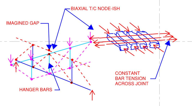
 
I think the same tension through the nodal zone from the supporting beam I have been talking about is load of rubbish on further reflection, because in effect you have these two intersecting 'beam' trusses, they share the same vertical tie/strut at the point of overlap. They have to, or it's not a valid S&T model to get load from one beam to the other!

I was somehow trying to explain away there being no impact on the other direction by passing reinforcement through without change in tension, but this is impossible in a valid model of the OP's scenario... eureka moment?!

So the bottom of the supporting beam has a diagonal strut coming into it in both directions, tension/compression vertical, in one direction horizontal compression strut from cantilever beam each side, in other direction horizontal tension tie from bottom reinforcement of supporting beam.

So at least 2 anchored ties from various directions, so now see you need to take 0.6 reduction for the entire 3D node (buggered if I know what this actually looks like in practice with all those ties/struts coming together).

I guess while codes don't provide any generalised rules around this situation, they do in fact provide for allowing strut and tie in D regions. This is a D region where there is a force discontinuity in delivering the reaction from cantilever to supporting beam if ever I've seen one. In saying that I backup the earlier statements that does anyone really look at it this way for practical design. Should we be?
 
Well, with your 3D strut and tie example, you've got me wondering on some things.

Agent666 said:
I think the same tension through the nodal zone from the supporting beam I have been talking about is load of rubbish on further reflection, because in effect you have these two intersecting 'beam' trusses, they share the same vertical tie/strut at the point of overlap.

Yes and no. Obviously, the girder stirrups and the cant beam hanger steel occupy the same physical space. That said, they don't share function really. In my mind, the hanger steel is used up in the act of of hanging and is not part of the shear truss model of the girder. Our biaxial stuff excepted, once the supported beam is "hung" it's almost as though it were now mounted above the girder.

Agent666 said:
I was somehow trying to explain away there being no impact on the other direction by passing reinforcement through without change in tension, but this is impossible in a valid model of the OP's scenario... eureka moment?!

I'm not so sure. I really do not see the top steel tension in the supported beam changing appreciably as it crosses the joint. I see that STM looking like a flat bottomed vee tied across the top. Are you seeing that differently?

Coming back to your earlier work...

Preliminary:

When a tie crosses a strut not at a node, I personally feel that there should be some reduction applied to the strut capacity. Sometimes, after all, we take active measures to confine our struts. So it's hard for me to imagine that struts are not weakened by the introduction of a crossing tension field.

A Reformulation of Your Argument (Maybe):

1) Codes have you apply a strut capacity reduction when tension ties cross at a node.

2) Codes do not have you apply a strut capacity reduction when tension ties cross away from nodes.

3) What is one obvious difference between #1 & #2? At a node, the tie tension is changing across the strut. At a non-node, the tie tension is not changing across the strut. This is sort of by definition as, in an STM, bar tension can only be changed at a node. So perhaps you don't actually have a node from the perspective of the tie unless the tie force is changed at the node.

4) 1 + 2 + 3 --> if tie tension isn't changing, it's not a node. Or, at the least, it's not a node that the tie is meaningfully participating in.

This is me trying to think like you. What do you think of that? This still doesn't say much about why changing bar tension should be the thing that matters but it is, at least, circumstantial evidence that it may in fact be the thing that matters.

You're right, of course, in that the 3D STM here makes the top of the joint a "node" because the hanger steel and two girder struts meet there. But it may not be a node from the perspective of the cant beam top steel because no axial force is imparted to the top steel at the joint. Pass through.

Agent666 said:
Should we be?

My feelings on this are related to the cleat business in the other thread. I believe the following to be true:

1) Our field is, out of practical necessity, reactive and not proactive. To the uninitiated it appears that we know of all the possible failure modes, evaluate them, and then take a coffee break to celebrate a job well done. In reality, we know of only the failure modes that have previously plagued us, design for those alone, and cross our fingers that other terrible, unforeseen failure modes will not occur.

2) We suck at first principles connection design. Via Northridge, steel cleats, and the rest we seem to perpetually have egg on our collective faces in this realm. It's frankly hard to look at the situation objectively and avoid the conclusion that no connection should be allowed unless it's been vetted through testing.

There's an adage out there to the tune of:

Any bozo can design a member. It takes an engineer to design a connection.

That should be revised to:

Any engineer can design a member. It takes a federally funded research program and/or a sprinkling of pixie dust to design a connection.


HELP! I'd like your help with a thread that I was forced to move to the business issues section where it will surely be seen by next to nobody that matters to me:
 
Agent666 said:
buggered if I know what this actually looks like in practice with all those ties/struts coming together

Not easy...

c01_nukiwy.jpg


HELP! I'd like your help with a thread that I was forced to move to the business issues section where it will surely be seen by next to nobody that matters to me:
 
The 1987 Schlaich et al paper that kick-started strut & tie suggested a factor of 0.8 when the strut has cracks parallel to its axis which probably applies here. If that's the correct order of magnitude, a beam that is 'properly' under-reinforced (nowhere near balanced reinforcement) shouldn't see much reduction in strength.

The 1994 CSA code apparently had a factor for strut strength where crossed by reinforcement that varies according to angle of crossing.
 
Are you seeing that differently?
For the most part seeing it the same, though until it was drawn out by you in the image I wasn't appreciating the inverted 'V' struts in the cantilever (and possibly also in the supporting beam depending on magnitude of load and location of load). Most of my comments were based on the bottom of the intersections, but I see they also can apply to the top which to be fair is probably a better example with the vertical separation you've factored in.

This is me trying to think like you
You've achieved this if your head hurts.

What do you think of that?
But it may not be a node from the perspective of the cant beam top steel because no axial force is imparted to the top steel at the joint. Pass through.
Yeah for the most part those were the concepts I was endeavouring to try to explain away in the fact that this is never checked.

Not easy...
In reality of course it's potentially considerably more complex because each beam might consist of 'truss model' each side of beam to deal with any torsion thats present. But the basic concept of the two overlapping trusses was what I was envisaging for the generalised coarse model of load transfer between the two beams.
When I made the comment regarding what it looked like I was actually meaning the complexities of determining the shape of the nodal region itself, this gets pretty funky to imagine and probably involves fiddling with the cross sectional shape of incoming struts to simplify things as much as possible. Considering you need to work out stresses on the nodal zone faces, you sort of need to do this. Pretty simple exercise in 2D, but 3D implementation has me scratching my head of a practical means of doing it in this situation.


It's interesting that the nodal zones in a normal beam truss pretty much always anchor somewhere in the model two or more ties, in the more complex overlap of beam trusses you are still anchoring two or more ties as well (just a 3D vs 2D situation where you might have a few extra struts/ties coming in transversely).

So the reduction factor for the S&T modal for nodal zone checks is still the same whether 2D or 3D. Perhaps this is a case for where we design a normal isolated beam using normal flexural theory we forget about all this strut and tie nonsense out of convenience because we aren't going to do it for all normal beam design. A cross section check inherently works, and strut and tie is more a means of trying to justify why it might work in a more 3 dimensional sense.

Similarly when we extend this to the beams overlapping, the net effect is sort of the same and we can also forget about the strut and tie nonsense because its still an extension of the normal beam design cross section check (due to similar reductions occurring at nodal zones if we delved into S&T world to try explain the three dimensional complexities or extend our two dimensional understanding to the third dimension with some transverse things going on).

 
Status
Not open for further replies.

Part and Inventory Search

Sponsor