Continue to Site

Eng-Tips is the largest engineering community on the Internet

Intelligent Work Forums for Engineering Professionals

  • Congratulations KootK on being selected by the Eng-Tips community for having the most helpful posts in the forums last week. Way to Go!

Big Holes in Glulam Beam 3

Status
Not open for further replies.

SarBear

Structural
Mar 14, 2022
38
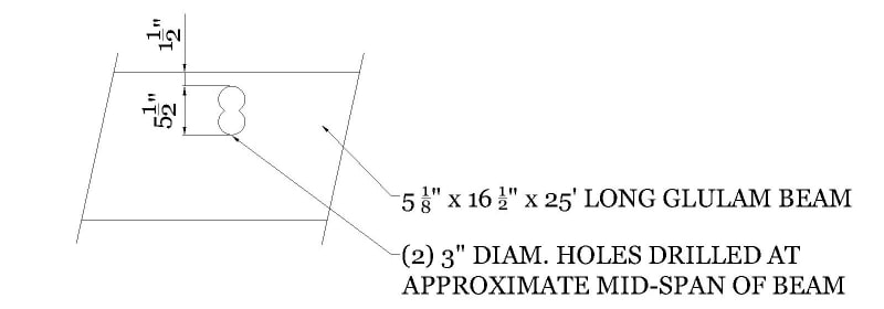
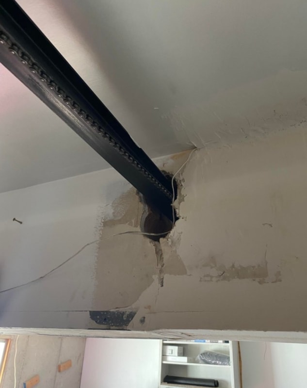
Hi all, wanted to get some feedback on this. A potential client approached me saying that they are wanting to buy this home, but the inspector noticed that the 5 1/8" x 16 1/2" glulam beam in the garage has some large holes drilled through it for the garage door opener. See the drawing below for the approximate dimensions of what's going on. The beam is about 25' long and is bearing the exterior wall of the second floor above. The selling agent has said that their engineer will provide a design where there are steel plates on each side of the beam that bridge the gap where the holes are and will have bolts going through. That sounds like a fine solution to me, but I'm not smart enough to be able to prove that this fix actually works.

The buyer has asked me to provide a second opinion since he is not sure about the proposed fix. The other engineer hasn't provided any drawings or calculations yet, so I'm not sure whether the fix will be legit or super janky. What do you all think? Is the steel plate idea doable? Is it provable? My feeling is that the solution is doable, but I'm too stupid to figure out how to prove that it works.
Beam_Hole_fnfmmu.jpg


Screenshot_20230511-224413_Messenger_rtsgfk.jpg
 
Replies continue below

Recommended for you

Geez! Wouldn't you love to get your hands on the neck of the moron that drilled those holes. In fact, if I was the owner trying to sell this house, I would be hunting down the person responsible and getting my pound of flesh.

Anyway, the proposed solution of steel side plates to reinforce the beam could work if done right, but it will have to be proved by calculation. The general principle I have in mind would consist of providing steel side plates to supplement the moment capacity of the reduced glulam beam section. The connection between the steel side plates and the glulam will have to be able to transfer the bending moment from the steel side plates to the glulam on either side of the reduced section. This will probably be the trickiest part. I don't think thru-bolts are a good choice because the slop in the holes will allow for some rotation of the joint before the moment capacity can be developed. I think lag screws would be a better choice, but that may present a problem of interference when installing from opposite faces of the beam.

Considering the cost of engineering and the poor quality of construction that can be expected for anything remotely outside the box in residential construction, it might be better to replace the glulam instead of attempting to reinforce, because I doubt very seriously whether the reinforcing will be done right.
 
Would we even have jobs if plumbers and electricians didn't butcher some piece of the structure on a house? Might be unemployed if they drilled per code.

This is a bad one. I hate seeing the holes or notches right at the top or bottom of a member. And this is a big beam presumably carrying a lot of load so it's not just a floor joist that's a quick fix.

For me I'd start with capacity vs applied load. Just to give me a starting point about how far off this reduced section is in strength. Plywood vs steel plates vs steel channels/ angles could all be used as a repair. If this thing isn't even close to working then I'd probably look to use a C8 or C9 channel for reinforcement instead of trying to get some repair detail to transfer a lot of moment capacity.
 
Looking at load tables a glulam of that size could have a 50 kip*ft or so moment capacity. At the depth we are talking, if the load is maxed out, you would have about 40 kips of compression at the top near the holes. If you could max out stee that is over 1 in2 of steel needed. Maybe L2x2x3/8 on each face with a ton of anchors back could work so you don't have to remove the garage door track to accommodate. If a lag screw is only good for a few hundred pounds it will take many anchors on each side. You certainly don't want to make swiss cheese of the whole thing with hundreds of anchors.

Best bet may be to see if the garage door can be altered to not run through that hole so a full depth member can be provided, but that may need to be full length on both sides to make good sense.
 
Tell the buyer you will review the engineer's calcs and provide feedback. For the little money you would make, probably not worth the headache.
 
repair: remove door opener; r&r gluelam beam. I wouldn't buy that mess.
 
Where is the project located? What is the grade of glulam? V4, V8 if west coast, custom laminations? First order of business is definitely determining what kind of product you have installed here. As you no doubt are aware, glulam beams have different strength laminations throughout the member (higher strength laminations to resolve tension/compression, etc). since this grouped hole is not located in the 'core' laminations in the center of the beam, you'll have more reduction in moment capacity than just the net section loss due to the hole through higher strength laminations, which you will need to calculate and determine if adequate.

You can always try and look at American Institute of Timber Construction (AITC) technical note 19, which discusses holes/notches in glulam. Believe AITC was rolled into the Pacific Lumber Inspection Bureau, so if searching online, you'll likely find the document on a plib website.
 
I would imagine you'd get a decent amount of deflection in the beam before it would start substantially engaging the bolts and plates. As it's the compression flange I wonder if there's something you could pack in the holes that would perform better than a steel plate.
 
I've been hesitant in the past with side plates and bolts/ through bolts - you currently have the inherent stresses in the glulam due to the self weight, so any repair is likely to only manage the increase in those stresses (i.e. imposed loads) unless you can prop from the underside to relieve the stresses whilst doing the repair.

You mention it is in the garage, would it be feasible to introduce a column to the underside of glulam and place a new footing through the garage floor? Far easier to quantify the load path but at the cost of reducing floor space?

 
Thank you everyone for your feedback, I appreciate it!

MRob909 said:
would it be feasible to introduce a column
Unfortunately this beam runs across the garage in such a way that any column put in would be right in the way of where the cars would drive into the garage.

jerseyshore said:
This is a bad one.
Yeah when I saw the pictures I couldn't believe my eyes
 
I didn't know glulam have different strength laminations in each section so thanks for that bit of info CD. I specify or check a glulam once every few years since they are very rare in this area.
 
jerseyshore said:
I didn't know glulam have different strength laminations

I'm not sure how glulams are built on the east side of the US, but the Doug Fir glulams we have out west are built with different laminations. It always gets fun when you have an architect that wants to have an exposed glulam, and you're required to achieve a 1-hour fire rated floor/ceiling assembly. Generally speaking, it requires a custom manufactured glulam with extra tension laminations on the bottom side to provide a char layer.

The link below I found on a quick google search, appears to do a decent job of explaining the concept.

 
I should add, I forgot about Comb3 glulam, which is a uniform layout glulam. These are generally only specified for column applications.
 
Great link, thanks!

Glulams are so rare around here. The last project I did with glulams was a big custom house about 3 years ago, but the architect was from Colorado. Good to have that info for when it eventually comes up.

Even more of a reason not to mess around with this beam disaster.
 
SarBear said:
The selling agent has said that their engineer will provide a design where there are steel plates on each side of the beam that bridge the gap where the holes are and will have bolts going through. That sounds like a fine solution to me, but I'm not smart enough to be able to prove that this fix actually works.

A plate each side should work, but glulam rivets would be a better means of attachment than bolts or lag screws as they would have less slip.
 
In 1-1/2" you can get a single row of glulam rivets... might be a little tricky with shear lag... If glulam beam shear OK then compression may be fixed by filling hole and relocating the holes to somewhere more appropriate.

-----*****-----
So strange to see the singularity approaching while the entire planet is rapidly turning into a hellscape. -John Coates

-Dik
 
A few things catch the eye here.

1) This beam appears to be clad in plasterboard, presumably fire protection? This needs to be removed over the affected beam plus 1m to see if the beam has started to exhibit any signs of distress / delamination
2) Has the beam actually moved / sagged?
3) Is there any signs of movement / cracking / sagging in the walls above inside or out?
4) If the beam hasn't moved could you add a C channel under it to add some strength if it does?
5) The issue is really that if the beam hasn't moved, any reinforcement won't do anything until there is some sort of movement / sagging surely?
6) That bit of the bean is surely in compression and maybe there is enough of the beam left that its loss of strength is not actually crucial?
7) If it has sagged then it needs propping to get it back to its shape plus some more before adding any reinforcement
8) Could you sister it either side below the garage door mechanism?

Remember - More details = better answers
Also: If you get a response it's polite to respond to it.
 
If it's supporting a wall above there is a decent chance the wall will act as a deep beam and just span. Not saying that's a good idea but houses are really good at finding alternate load paths.

I had a neighbor a few years ago whose garage header had a noticeable sag. We joked that the house had a smile. Turns out he had a leak that had been happening for years and had completely rotted the header above his garage door. This header supported a 2nd floor and roof. From what I could tell the wall for the 2nd floor was carrying the load.
 
Yeah, it “might” carry the load, and a repair “might” be possible, but would you buy a house with that mess? I wouldn’t unless they replaced the beam.
 
Status
Not open for further replies.

Part and Inventory Search

Sponsor