Continue to Site

Eng-Tips is the largest engineering community on the Internet

Intelligent Work Forums for Engineering Professionals

  • Congratulations KootK on being selected by the Eng-Tips community for having the most helpful posts in the forums last week. Way to Go!

Blade cutting area 1

Status
Not open for further replies.
Dec 22, 2022
4
Hey guys! I hope you're doing well!

I need to build a device that makes a circular cut in a single hit on a steel plate, using a pneumatic cylinder. For this, I need to estimate the force that the cylinder needs to make the cut, as shown below.
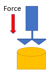
scheme_g7pyxg.png


The diameter to be cut is around 100 mm.
The compressed air line pressure is 6 bar.
The thickness of the AISI 1020 to be cut is 0.5 mm.

What intrigues me in this case is how to consider the contact area between the blade and the plate, since I intend to manufacture something like the image below.
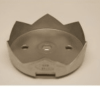
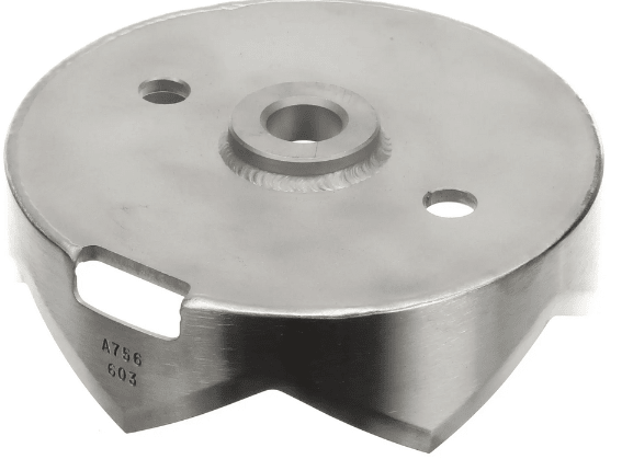
blade2_r2bcwi.png
blade1_vhkmtm.png


Why do I want to use this geometry? I strongly believe that the cutting force vs cost ratio is more advantageous, precisely because of the area.

My plan is to estimate the shear force, and then with the air pressure used in the cylinder find a cross-sectional area to select the proper cylinder, assuming a 15% "safety factor" for the cylinder.

Are there any tips or tricks for considering the area of this slide and find an analytical solution?

Thanks in advance for the support, guys!
 
Replies continue below

Recommended for you

How many cuts do you figure you will need to make?
Is the goal to create 100 mm disks, or to punch one or multiple a 100 mm hole in a panel?
In either case ejecting the disk from the cutter probably needs to be considered.

Compressed air might store up a bunch of kinetic energy during the cutting process, and release it pretty angrily and in unexpected ways at the end of the cut, or if something goes wrong during the cut.
Hydraulics might be safer, like hydro-testing pressure vessels etc.
And and provide greater reserve push if needed as the tool dulls, etc.
Pressure washers are (MIS-)used for a variety of grass roots projects.
 
That's going to be rough to manage - the tapered cutting edges will force the small diameter dimension of the cutter in the surrounding material to expand to the large diameter of the cutter. Without a stripper mechanism that surrounding material will be tightly sprung around the cutter.

Typical punches don't have that diameter change so they don't require so much force.

Even at 0.5mm I would not expect a pneumatic system to be a good choice unless it is used to raise a drop-hammer.
 
@Tmoose and @3DDave, thanks for your reply! Actually, the blade is for opening food cans in an industry. Sorry for not having announced the application. I believe that for this application, there may be a solution, but I don't know if analytically I will have any result, or if I should simulate it in some software.
 
Unless the idea is that no one will make a prototype, buy a cutter and try it. You might also measure the force required for a can-opener to initially pierce the can - multiply the hand force by the leverage; that should be higher than the force to continue the process.

Not the first time it's been asked, but no happy answer:
 
Blanking Force = Perimeter of the Cut × Plate Thickness × Shear Strength

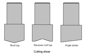
with the inclusion of "shear" on your punch, you could derate the blankiing force - a conservative estimation would be to use the formula above.

punch_shear_tt4hwy.gif


A reasonable value for shear strength for steel would be 75% of tensile strength (not yield).

A visit with a local tool and die maker would probably speed along your development, in particular with regards to the stripping of the can lid from inside the punch. A good die shop will know several techniques.
 
I watched a video of a maker of a delidding system using this cutter and the cutter is designed to not capture the lid - just leaves it in place for a magnet to fish out.

I'd include a link but I don't support vendors who require marketing information to get a PDF download brochure. Sure I can "unsubscribe any time" but I don't want to subscribe or waste the time of the sales guy or get my info sold to put me on other lists.
 
@3DDave, thank you very much. In fact, I didn't look up the term "pierce", just for "cutting". One more mistake of mine. Also, I watched a video, may be, the same of you watched. I need to do something like that. Unfortunately, they ask for too much personal information for a simple pdf, and it may not contain the information I need.

@dvd, you gave me a light. Thank you very much.
 
Many Manufacturing Processes course textbooks that have chapters on sheet metalworking will give an equation very similar to dvd's:

F = 0.7 x T x L x (UTS)
T = thickness of material
L = total length of the sheared cut(s) performed in the single pass of the press
UTS = Ultimate Tensile Strength of the material

or, if you have data on Shear Strength, then it becomes F = T L (SS)

TygerDawg
Blue Technik LLC
Manufacturing Engineering Consulting
 
The shear length will be .5mm*cos(blade angle)*number of blades*2 (number of edges per blade). Obviously the limit is the cutter perimeter length with a single circular blade - cookie cutter style.

There is also bending of the can rim on the outside of the cutter because of the blade geometry. This will guarantee clearance for the magnetic lid lifter.
 
Your design ostensibly requires 6 times the force of a normal can opener initiation, since there's usually only one blade, instead of six. Unless you have ultrafast stopping control, you're likely going to slam the cutter into the soup can

TTFN (ta ta for now)
I can do absolutely anything. I'm an expert! faq731-376 forum1529 Entire Forum list
 
@tigerdawg thank you very much. I will use this correlation to check the force conservatively.

@3DDave you rock, man! Your correlation Will be usefull and totally makes sense.

@IRstuff I believe that with some valve the extension can be easily controled.
 
Status
Not open for further replies.

Part and Inventory Search

Sponsor