Eng-Tips is the largest engineering community on the Internet

Intelligent Work Forums for Engineering Professionals

  • Congratulations waross on being selected by the Tek-Tips community for having the most helpful posts in the forums last week. Way to Go!

Blind Rivet Use Cases 1

Status
Not open for further replies.

EnginerdNate

Aerospace
Feb 4, 2019
84
0
0
US
I'm currently looking into using flush head blind rivets on a simple system I'm designing. I have come across several different rivet specs and very little information on which rivets typically get used for specific applications. Specifically, I've seen a lot of references to the NAS1921, NAS1399, and MS90353 specs, the first two being true rivets and the last usually referred to as a blind bolt. I'm a bonded composites guy normally and the tribal knowledge at my current job is a little thin.

Can someone provide the cliffs notes for aerospace grade blind rivet types (If you like, including any you like that I've not found so far) and their applications? MMPDS-10 has no data for the NAS1399 for installed strengths, so my gut check says it may be falling out of favor if they aren't bothering to keep the data updated.

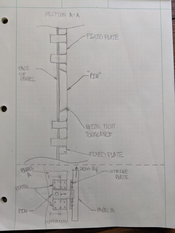
My application is a medium load (~2000 lbf shear limit load) single shear joint between two flat plates. I am constrained to using flush head fasteners due to space constraints and am looking at rivets to avoid the need for a complicated blind-fastener system.

I have some other features that make locating the part simple, so match drilling through an undersized pilot and pulling 4-8 blind rivets seems like the simplest solution to my problem.

Thanks,
Nathan
 
Replies continue below

Recommended for you

I have a lot of experience with blinds of all types....MIL acft cannot be assembled/repaired without blind fasteners.

I also Have a massive fastener and associated hardware cheat-spreadsheet [built over many years] to select from... but little time to help You, right now.

Questions for YOU...

What application and what materials/thicknesses?

For a homebuilt or low-volume production project Acft [or similar]?

Cherry fasteners have lots of BR and BB styles/materials/finishes/strengths to choose from and lots of data... good place to start 'looking'...
Other BR/BB fastener manufactures...
ALCOA FASTENERS [HUCK, ETC] ALLFAST Avdel
Many more NAS/MS styles of BRs to select from, than You have mentioned.

Real Issues/problems I have found with BRs BBs...

Sizes [Diameters] are not as straight forward s desired.

Oversizes exist... but no conveniently.

Many material types for the sleeves. pins, lock-rings, etc... and finish options are not always 'the best'.

Hole size is critical... and must be tightly matched to the fastener.

Lesson-learned... I NEVER design/analyze to ultimate joint strength... I always analyze to joint yield as real-world joint ultimate... which is counter-intuitive/inconvenient but necessary/conservative due to BR install/environmental/fatigue factors.

Useful ... if somewhat 'dated'... references... [Plus Cherry installation guidance documents]...

MIL-STD-405 RIVETING, ROCKET AND GUIDED MISSILE STRUCTURAL, ALUMINUM AND ALUMINUM ALLOY BLIND RIVETS, MECHANICALLY EXPANDED TYPE

NASM1515 [MIL-STD-1515] FASTENER SYSTEMS FOR AEROSPACE APPLICATIONS

NASM33557 [MS33557] NONSTRUCTURAL RIVETS FOR BLIND ATTACHMENT; LIMITATIONS FOR DESIGN AND USAGE

NASM47195 [MIL-R-47195] RIVETS, BLIND, SELF-PLUGGING, PREPARATION FOR AND INSTALLATION OF

NASM47196 [MIL-R-47196] PREPARATION FOR AND INSTALLATION OF BUCK-TYPE RIVETS

MIL-HDBK-5s... but not so-much MMPDS...

NOTE.
My 'secret-favorite' BR for thin-skins... where low-head-height but not deep countersinking is required in the air-flow... is the 'Unisink' head style [as developed by Cherry]... otherwise known as 'Flange Domed head' [NAS9306 and NAS9312]... with 'cherry-max' installation features.

Regards, Wil Taylor

o Trust - But Verify!
o We believe to be true what we prefer to be true. [Unknown]
o For those who believe, no proof is required; for those who cannot believe, no proof is possible. [variation,Stuart Chase]
o Unfortunately, in science what You 'believe' is irrelevant. ["Orion", Homebuiltairplanes.com forum]
 
Start with fasteners you can actually acquire and afford to buy.
I find the Huck CR3213 can be cheaper, and pull better, than the equivalent Cherry fasteners, but CR3213 is more common.

No one believes the theory except the one who developed it. Everyone believes the experiment except the one who ran it.
STF
 
why blind fasteners ? (there are reasons, but not explained)

Is this part of the pressure vessel ? primary structure ?, secondary structure ?

How thick is your s/metal ?

Is this loaded in fatigue ?

another day in paradise, or is paradise one day closer ?
 
Fatigue should not be an issue.

Blind because the system mounts to a cored panel with tubular aluminum closeouts that have internal features that preclude access from the back side for installation of a standard nut + washer.

The total grip is ~.625" with the fastened metal plates making up .25" of that stack up.

Primary structure but on a non-airborne component. This particular part of the system is only ever deployed on the ground. The primary reason I posted in this forum was due to the construction (cored panels) and hardware (NAS/NASM) being most frequently used on aircraft. Our factory makes numerous aerostructure components as well so this system is designed as if it were for an aircraft when it comes to hardware choices etc because that's what the techs/engineers here are familiar with. The primary difference here is use of aluminum skins instead of composite as with our aero components.

Simplified diagram of the joint below. All fasteners mount to the extruded aluminum tube at the edge of the panel. I'm at home at the moment and in the middle of a move so I couldn't find a ruler, apologies for the wonky lines. The gap between the panels is exaggerated, but there is roughly .25" between the panels. This in part drove the desire to use a rectangular pin, as the diameter of round pin required to take the induced bending load was never going to fit in the space required. I have a hard .25" limit on out of plane space from the perspective of Panel A.

2019-05-25_09.53.47_fhtnmy.jpg


Conceptually it's like a door latch except the primary load is in shear as shown. No "out of plane" loads to speak of, they're taken by other components in the assembly. I'm considering using the trapezoidal geometry shown to make the pin captive without having a stepped profile or the need to have a retaining plate over the top of the plates shown. There are other features not shown that lock the pin into place in the retracted or deployed positions. To get good shear transfer, I need to have relatively tight tolerances between the fixed plates and the sliding pin, so my thought was to hard locate the strike plate and float the fixed plates on panel A in around the pin with some 0.001" shim stock on either side of the trapezoidal faces and match drill/ream the panel and plates and install with blind rivets/bolts of some flavor. My thinking here was to eliminate the need for threaded inserts and or rivnuts of some flavor and the tight machining and assembly tolerances that would be required to keep the tolerances between plates AND the fastener patterns happy. Machine pilot holes in the fixed plates, locate, clamp, match drill, ream, pull. Design so that if the plates every need replacement there is edge margin and space for the next size up fastener.

I eliminated the NAS1399 and NAS1921 options late yesterday, some of the mentioned internal features on the extruded tubular closeout interfere with the backside of the rivet in the unpulled state so they can't be seated down to the surface of the plate properly. the MS90353 looks like it will fit as it has a much shorter unpulled length vs griplength in comparison.

Thanks,
Nathan
 
Forgot to mention, the trapezoidal shape shown is highly exaggerated, I'm looking at something like 5* on each side. Something as extreme as what's drawn would cause enormous prying loads when loaded up.
 
oooh … riveting cored panels … not a good idea, and blind riveting, worse. The rivet stem won't seat well on the far side, and crush the core.

If you Have to do this, then I'd suggest
1) use threaded inserts and screws,

2) counter-bore the open face so you're riveting onto the laminate face. "repair" the counterbore (and reinforce the face) with some RT wet lay-up fibre glass plies. And spacer (or grow-out on the plate) to get you back to the near side face (of panel B).

What is the face material of panel B ? If Al you have a chance, if composite your bearing allowable is very small.

Is 2000 lbs ultimate load ? Maybe, if this is only a ground (like GSE) load then you don't Need to use ultimate factor as this is not a flight safety thing, "only" a durability concern.


another day in paradise, or is paradise one day closer ?
 
oh, and btw there are no "cliffs notes" for this (or anything else) … pretty much everything we do is dependent on the details.

If we do give solutions it's for what we've been told of the problem (usually not everything) so the answer may miss an important point.
If we do give solutions we'll err on the side of conservatism … then someone there can/will critique the solution as "wasteful".

Usually all we can give are some clues for things we'd look at first. We don't know you situation, your company's referable approaches ...

another day in paradise, or is paradise one day closer ?
 
Sorry, I must have been unclear. I rewrote that post so many times that I got auto logged out and the forum threw away the final version, I tried to recreate it as best I could but it's not perfect. The core ends a few inches from the edge of the panel and there's an extruded aluminum channel the same thickness as the core that runs along the perimeter of the panel. All fasteners will go through the skin into the interior of this [hollow] channel, no core involved. So the stackup is shear plate-skin-nominal bondgap-tube wall.

All facesheets are aluminum, so aside from the fact that there's a small bond gap between the aluminum skin and the extruded aluminum channel on the edge of the panel, it's as if I'm fastening to a hollow aluminum tube. I should have made that clearer in the section cut.
 
ok so "panel A' is the cored panel, with the core removed and the two face plies only … that's be fine.

is "panel B" the tube you mentioned ?

what's this 1/4" gap you mentioned ?? Or does your sketch show two views of your installation … with the upper view being a section through the LH part (panel A) of the lower view ? So that the gap is between these two pieces (panel A and panel B) and you fitting, attached to panel A, is bridging the gap and panel B is applying 2000 lbs of load ?

another day in paradise, or is paradise one day closer ?
 
Sorry my drawing is so vague. I've tried to simplify it to get rid of anything proprietary etc and made it confusing in the process.

Panel A and B are separate panels. B is coming out of the page and it's far end terminates in line with the "back" wall of A. Both panels have identical construction, core with a tubular aluminum perimeter frame. Ideally all fasteners will go through this frame member, as potting threaded inserts into the core is slow and expensive in addition to being less structurally capable.

Am I correct in my understanding that the MS90353s do not expend in the shank region and that this is part of the distinction between blind bolts and rivets? (I realize some rivets expand more than others as well)

Thanks!
Nathan
 
A couple of quick/dirty ideas for this joint/assy...

1. Install with blind rivets.

1.1 BRs can be installed thru honeycomb panels as You have described... but ONLY if following criteria are met...

1.2 The backside sheet is thick enough to support the blind tail formation.

1.3 Blind rivet MUST be available with necessary 'grip length'... which may-NOT be practical for small Dia fasteners.

1.4 Pilot-drill the hole for the BR thru the top-sheet; then create a small cavity thru the honeycomb-foil [on-axis with the hole]. Make the cavity using a sharpened wire blade made from a piece of ~0.062-to-0.091-Dia music wire with the end bent-sharply-over to 90-Deg, 0.18-to-0.32 long... then sharpen the bent-end to make a [circumferential cutting] knife-blade edge. I THINK MIL-HDBK-337 has a figure showing 'how-to-make' and 'how-to-use' the cavity cutter. Inject-fill-pot the cavity with low-viscosity epoxy resin and allow the resin to fully-cure. Once the resin has cured, then drill the 'full-Dia' BR hole thru the center of the 'resin plug' and out the back-side sheet.

1.5 Install Your blind-Rivets.

2. Install/assemble the panels with screws into nutplates.

Match-drill pilot-holes thru the honeycomb panels.

For each honeycomb layer make an epoxy-resin plug... then drill the full-size bolt-holes.

Install a 'Click-Bond' Nutplate to the hidden side of the panel.

Assemble Your Joint.

Regards, Wil Taylor

o Trust - But Verify!
o We believe to be true what we prefer to be true. [Unknown]
o For those who believe, no proof is required; for those who cannot believe, no proof is possible. [variation,Stuart Chase]
o Unfortunately, in science what You 'believe' is irrelevant. ["Orion", Homebuiltairplanes.com forum]
 
It looks like the grip lengths I need are readily available in both the S05 and S06 sizes of the MS90353 blind fasteners, and I've got at least one designer here saying we use the MS90354s (protruding head version) elsewhere in the shop so we should have the tools and training in place to install those.

Regarding installing in the panel, the rivets won't be in the cored portion of the panel. If you looked at a cross section of the panel, the core would end x" away from the edge and the extruded square tubing closes it out instead of having the edge potted. The backside of the fastener holes will be bare aluminum. I'm thinking if we use a reamer to finish the hole there shouldn't much of a backside burr to worry about.

I'm considering adding a couple of potted inserts that match up with a set of slotted holes + button head fasteners on the plates to make assembly easy-no additional clamping needed. Rivet pattern designed to take the entirety of the load, the button heads could even be removed once the rivet install is complete. Being a groundside piece of equipment relieves the hardware weight constraints a bit. This would also make field repairs easier if they became necessary as there would be a feature holding the plates in place while the rivets got drilled out.

Install sequence would be:

1. Hard locate strike plate-likely during panel fabrication.
2. Temporarily install pin to strike plate
3. Install plates on panel A with slotted hole fasteners, gap with shim stock or feeler gauge, torque fasteners.
4. Match drill+ream
5. Rivet.

Thanks,
Nathan
 
OK...

MS90353 blind-bolts can exert a significant backside-force at the hole edge during tail formation. Suggest careful testing to avoid localized deformation/crushing at/around the hole.

Have You considered using Monogram Composi-Loks for 'softer backside [tail-forming] forces'?
Regards, Wil Taylor

o Trust - But Verify!
o We believe to be true what we prefer to be true. [Unknown]
o For those who believe, no proof is required; for those who cannot believe, no proof is possible. [variation,Stuart Chase]
o Unfortunately, in science what You 'believe' is irrelevant. ["Orion", Homebuiltairplanes.com forum]
 
I have not, we used those on a project at my college internships ages ago, I thought they were specifically for composite skin applications.

I guess logically things designed specifically for composite skins are primarily designed not to have too much clamp up force and maybe a smaller countersink, which wouldn't preclude use in metals in any way.

Out of curiosity, is there any general consensus on pull mandrel vs screw thread mandrel type blind fasteners? Superiority of one vs the other or pros/cons of each?
 
The biggest limitation in this application looks to be the C dimension (unpulled total length) shown in the Huck documentation for the MS90353. Too long and I have an installation problem even if the pulled fastener would fit. I can adjust the fastener pattern to get more room but that may have negative consequences from a load bearing standpoint. Composi-loks seem to across the board have a large depth requirement in the unpulled state. If there's another option that has similarly low depth requirements to the MS90353 series but lower tail formation force I'm happy to check it out.

 
OK, OK...

What about a Cherry titanium MaxiBolt? These are similar-to MS90353 and MS90354 BBs, but have a much 'softer deformation' when the tail is formed. Also several flush head-styles are available.

I have specified use of these BBs thru aluminum honeycomb... so they should work in Your application.

[last 6 items on the list]

Regards, Wil Taylor

o Trust - But Verify!
o We believe to be true what we prefer to be true. [Unknown]
o For those who believe, no proof is required; for those who cannot believe, no proof is possible. [variation,Stuart Chase]
o Unfortunately, in science what You 'believe' is irrelevant. ["Orion", Homebuiltairplanes.com forum]
 
I'd say "no core" = "no problem". Blind rivets are pulled like this (against Al sheet/plate) every day.

another day in paradise, or is paradise one day closer ?
 
Status
Not open for further replies.
Back
Top