Continue to Site

Eng-Tips is the largest engineering community on the Internet

Intelligent Work Forums for Engineering Professionals

  • Congratulations KootK on being selected by the Eng-Tips community for having the most helpful posts in the forums last week. Way to Go!

BNC oscilloscope reverse polarity adapter ?

Status
Not open for further replies.

MRSSPOCK

Mechanical
Aug 29, 2010
303
I have searched for a few hours to no avail, for an adapter to connect to my oscilloscope probe, to reverse its polarity.

I have found some which look reasonably close to what I want,(but not quite, at extortionate prices). I only use a scope for simple pretty basic functions. I bought a Picoscope and was dissapointed to find that the INVERT function doesn't work very nicely. It inverts the waveform, but also displays the original. Then when you hide the original, the trigger diamond gets hidden also, but it's in the wrong place anyway, since it is on the opposite side of the zero line.

It's a pain in the butt.

The simple solution is a polarity adapter to fit on the end of the probe, but I can't find one anywhere. The closest I can find is an rfa 8333, but even though the connection ends are correct, the pin genders aren't correct. One side is and the other isn't.

One side needs to resemble the scope connection and the other the probe connector, but any I can find aren't like that.

Surely such a thing exists?

Am I looking for a jack -> jack, or a plug -> plug ?

Thanks

Here's an example of what I don't want, since both have a male pin internally.

I know I can make an adapter from bits and pieces but I prefer to buy the bespoke par if I can.

 
Replies continue below

Recommended for you

Then when you hide the original, the trigger diamond gets hidden also, but it's in the wrong place anyway, since it is on the opposite side of the zero line.

You should be able to move the trigger diamond by clicking and dragging it.
 
A differential amplifier or an isolation amplifier is what I use.
Otherwise, the math tool (A-B) is quite useful if you do not need extreme speed or accuracy.
It turns two grounded channels into one floating channel and by grounding the A and measure with B, I usually get the job done. If you want to apply a "global" minus [-(A-B)] to the result, it can be done.

Gunnar Englund
--------------------------------------
Half full - Half empty? I don't mind. It's what in it that counts.
 
Thanks for your suggestions, but I would sooner cobble together an adapter cable. I cant believe the adapter I want doesn't exist, and I'm amazed Pico didn't make it to invert just like a regular scope.

@mudandsnow, the diamond becomes invisible when you hide the original channel, so its a real pita to fine tune things when you have to keep turning the hidden channel back on, just to get at the diamond. And when the hidden channel is unhidden, the two traces superimposed on one another just becomes a big mess, and you can hardly even tell where it is you want to place your diamond.
 
The adapter you linked to in the original post doesnt actually reverse the polarity of the connections. The term reverse polarity is just referring to the pin and the threads being opposite of normal. Take a look at this video.

 
Interesting video. His definition of thread gender may be opposite to the definition of gender used by every other field.
eg:
Threads on the outside of a device = male for electrical conduit.
Threads on the outside of a device = male for threaded water pipe.
Threads on the outside of a device = male for hydraulic fittings.
Threads on the outside of a device = male for bolts.
Threads on the outside of a device = female for connectors.
But I saw it on the internet so I must be wrong.
If you reverse the polarity with the leads, you may be sending the signal to the frame of the scope.
Also the outer part of the connector will be at signal potential.
Possibly OK for signal work but don't do it on a power circuit.
Just ground your probe and use the ground clip to pick up the signal.
If that won't work, then a special connector may not work.

Bill
--------------------
"Why not the best?"
Jimmy Carter
 
"If you reverse the polarity with the leads, you may be sending the signal to the frame of the scope"

Not really an issue in this automotive application.


"Just ground your probe and use the ground clip to pick up the signal."

I wish it was that simple.

Unfortunately it has both ends terminated with crimped connectors.

It is a capacitive pickup so changing its orientation doesn't change the signal polarity unlike an inductive type.

Its a bit like this one.

 
OP said:
It is a capacitive pickup so changing its orientation doesn't change the signal polarity unlike an inductive type.
That's my point. If you can't reverse the signal by reversing the connections, then a special connector won't help.
A simple test:
wrap a couple of inches of tin foil around the cable to be measured.
Clip your ground clamp to the tin foil.
Clamp your inductive pickup to ground.
Check to see if that inverts the signal.

Bill
--------------------
"Why not the best?"
Jimmy Carter
 
@waross

"If you can't reverse the signal by reversing the connections"

Sorry I didn't say that, I said orientation.

By orientation I mean how you invert the inductive pick up on a strobe light in order to reverse the polarity of the signal.

(Strobe light clamps have a marker saying "THIS SIDE TO SPARK PLUG", but even that is only a suggestion. If you use it on a twin output coil, one spark plug spark jumps TO the ground electrode, and the mating spark from the same coil jumps FROM the ground electrode, so in such a case you really just have to try it and flip it accordingly).

This capacitive type pickup works different so flipping the clamp has no effect on the signal.

On the other hand, uncrimping the end and swapping how its terminated most definitely will invert the signal.

How can it do otherwise.
 
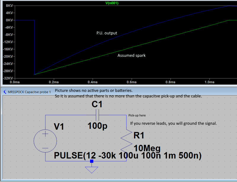
Not so sure how that pick-up is built. But it seems to be just a pair of steel plates connected to the center lead of the (RG58) cable. If you connect that to ground, the signal is shorted to ground. If, on the contrary, there is some sort of amplifier built into the probe, I do not see anything than an RFI core at that end, then it could work. Does the spec say anything about amplifier? Is there a battery in it?

If not, you have something like this:

MRSSPOCK_Pick_Up_1_zaxo7e.png


And then, a simple cable switch doesn't help.

Gunnar Englund
--------------------------------------
Half full - Half empty? I don't mind. It's what in it that counts.
 
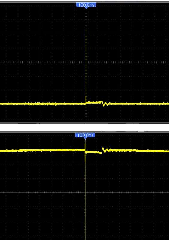
I'm sorry, but I really can't understand why people believe reversing the cables at the scope input will not invert the wave? If the potential has swapped around, the wave must invert. There is no other option. Below is the result of my test with this probe in question, in case anyone is in doubt.

cable_inverted_afssyb.jpg
 
If your scope is true differential, then you already have the isolation amplifier. And then it works.

But if you have an "ordinary" scope (yes, I know that you are using Pico, but not what model) then most models have a much larger capacitance from the "cold" (or GND) connector to Earth than from the "hot" (center) connector to Earth. And in most cases, there is a direct connection to Earth.

So, if you swap leads, you will load the signal (capacitively coupled spark signal) in a way that makes both quantitative and qualitative measurements impossible. And, if the cold connector is grounded, you will not get much signal at all.

The screen you show seems to be taken with a symmetrical front end. If so, your problem wasn't a problem from the beginning. What Model do you use? And what SW? The screen shown doesn't look like an ordinary Pico screen.

Gunnar Englund
--------------------------------------
Half full - Half empty? I don't mind. It's what in it that counts.
 
I'm afraid that is much too scientific for me. I just know I swapped the leads and got the result I wanted. I can't see how it can do otherwise if my signal source is a completely isolated entity from the oscilloscope. i.e. they have no common connection to a mains supply and hence don't share any kind of common ground. I just used my Hantek to prove switching the terminals would swap the trace about the horizontal axis. My ignition system is a car with no connection to earth, so it is completely isolated other than the cable coming from this capacitive pickup. If any independent scope is connected to such a pair of wires, and wire A is at a higher potential than wire B, I don't believe the scope can tell you B is higher than A unless the INVERT option is active on the said scope.
 
Yes, it is DC isolated. But a pulse like the one shown (known as a Dirac pulse) contains mostly high-frequency AC. And HF pours, like water through a sieve, through capacitance. So, even if the insulation is good for kV, you will not be able to do any measurements worthy of the name. If you are after timing only - then you don't have to bother much.

Gunnar Englund
--------------------------------------
Half full - Half empty? I don't mind. It's what in it that counts.
 
As you can probably gather, I am in no way trying to gather any accurate kV values, especially with a £10 probe from China :)

I just will use this for comparative tests in automotive applications.

On a Snapon scope, you press, INVERT and the jobs done.

Again, the Snapon is obviously not for doing definitive accurate voltage tests but rather comparisons.

I'm surprised Pico didn't include such a simple option by default.

I have since found that there is a way to define custom probe in their software which has a multiply factor.

It is simply a case of making this factor -ve 1 and the jobs done.

Thanks for everyone's input.

I'm now sorted :)
 
For future reference (regarding the original question): two BNC-Banana Adapters, genders as required, mated with a flip.

 
Status
Not open for further replies.

Part and Inventory Search

Sponsor