Eng-Tips is the largest engineering community on the Internet

Intelligent Work Forums for Engineering Professionals

  • Congratulations waross on being selected by the Tek-Tips community for having the most helpful posts in the forums last week. Way to Go!

Boiler Pressure 5

Status
Not open for further replies.

TendaiM

Electrical
Jun 21, 2017
8
0
0
ZA
Good Day

The problem is I have a pressurized boiler and the feed water is pumped into the boiler using a pump which gets its input from a frequency inverter. The frequency inverter gets its input from a controller which monitors the water level in the boiler. The concern however is that the pump is only able to overcome the boiler pressure, hence pump water, into the boiler after a certain frequency, which thus is giving the problem because pump in excessive amounts than is required.

The controller being used is a PI controller. We cannot replace the pump and we need to develop a revised water regulation algorithm. I am working on a model to calculate the expected amount of water to get into the boiler by using a look up table of speed at which pump can pump water versus the boiler pressure. Since I know pump capacity I can then calculate the amount of water which will be pumped in at a frequency at which the pump can overcome the boiler pressure.

Also I can find from a level transmitter the amount of water which has to go into the boiler, hence when water is eventually pumped, I just return the error amount back to the reservoir. We also have a turbine flow meter which measures the amount of water going into the boiler

However I feel that they might be a better and cheaper way of control. Maybe introduce a derivative term.

Can you please help me out on this one.
 
Replies continue below

Recommended for you

I am working on a model to calculate the expected amount of water to get into the boiler by using a look up table of speed at which pump can pump water versus the boiler pressure. Since I know pump capacity I can then calculate the amount of water which will be pumped in at a frequency at which the pump can overcome the boiler pressure.
Good idea. Do you have pump curves? Do you know what they are? Look them up.
The table idea would work but generating an equation would work too. I would learn towards an equation.
What would you do with the results of the table?

However I feel that they might be a better and cheaper way of control. Maybe introduce a derivative term.
Cheaper usually isn't better.
The derivative term will not help.
You seem to have the right idea with the table or equation.
Is the load on the boiler relatively constant? Do you need to worry about shrink and swell?


Peter Nachtwey
Delta Computer Systems
 
Howdy,
For continuity, I have attached the following replies form the original thread prior to you being asked to relocate to this folder.
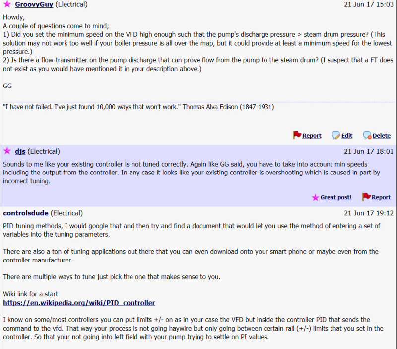
2017-06-22_12-38-28_fgmpsa.jpg


"I have not failed. I've just found 10,000 ways that won't work." Thomas Alva Edison (1847-1931)
 
Howdy,
The very nature of a PI controller should make this a simple loop to configure and tune. ie as the level drops in the steam drum, the speed of the pump is increased until the level is satisfied.
In theory, keep the pump running at a speed to ensure that the pump-pressure is > boiler-pressure (ie always flow into the steam drum).
The problem here is if the steam drum level is at or above setpoint, the pump speed will be decreased to a point where there is no flow (ie pump discharge-pressure < boiler-pressure). There is no issue here with the VFD or the motor, however the pump may not take kindly to running in this mode for very long. If this is a problem for the pump, then the only option that you will have is to turn the pump off until such time that the steam-drum level is below setpoint. At that time you can re-start the pump and enable the PI controller. The good news here is that with VFD control you can re-start the motor as often as required (without melting the rotor).[flame]
Does this seem reasonable?
GG


"I have not failed. I've just found 10,000 ways that won't work." Thomas Alva Edison (1847-1931)

 
Thanks for the help guys
@PNachtwey yes we have pump curves from which I can calculate the speed at which the pump should be running to overcome the boiler pressure at the moment
@GG so the general idea is to set the VFD to run at a minimum speed at which pump pressure can overcome the boiler pressure at which we are operating at.
 
Also something I had left is that our control is that the pump is turning on when level goes down and turns off when we reach the desired level. This works we are controlling to within 3mm of the set point but we want sort of a constant pump flow not this on and off behaviour
 
Howdy,
Yes, I agree with you in that the preferred method of operation is continuous level control, and not starting / stopping the pump. Stopping the pump would only be required if the steam-drum level is > setpoint for a period of time. This is only for the protection of the pump, since I assume that the pump does not like to operate in this mode for an extended period.
Stopping / Starting the pump should be a rare occurrence; it is only suggested here as a means to protect the pump.

Other means that I have seen implemented include a bypass loop around the pump to ensure a minimum circulation thru the pump at all times. This is as expensive option since you would require a control-valve on the bypass loop.
GG


"I have not failed. I've just found 10,000 ways that won't work." Thomas Alva Edison (1847-1931)

 
@PNachtwey yes we have pump curves from which I can calculate the speed at which the pump should be running to overcome the boiler pressure at the moment
Bingo! You have got it. Use the pump curves as your table. It would be better to have an equation. Yes you must estimate a new control output or bias or as a function of desired flow and actual pressure as the error and boiler pressures changes.
This will keep the pump running continuously.

The question is what should the desired flow be due to pressure and level error?
I have no clue as to how big your boiler is and it surface area. The bigger the surface area the more flow is required to reduce the error by a certain amount. You probably would want to correct the error within a minute or less so chose a desired flow that will do that. Do you know how to do that?

This bias term should be very close to providing the desired flow but it will not be dead on. That is OK. Now use the PI controller to correct for small errors in the feed forward or bias estimate. The controller will add or subtract the PI output to the bias to make the control output close to perfect. Use only a P controller and a proportional band. If you use a PI controller you will eventually get the error to 0 and the pump may stop unless you have a good way to estimate desired flow or have a third sensor to measure demand. You always want some error.

We still don't know the type of pump but at least we know it has a pump curve.

This is a classic case of people making recommendations without understanding the problem.
Bi-volt, your SISO will not work well here. There are two inputs, pressure and level.
There should be a 3rd input, demand. Then there would be no need to estimate desired flow.


Peter Nachtwey
Delta Computer Systems
 
by the way why haven't you a steam flow measurement?
That is what I meant by demand.
Back when I was in the navy we had steam generator water level control. The control had 3 inputs but I am pretty sure they were all proportional and linear. It was all done with magnetic amplifiers back then.
The difference between naval steam generators and boilers is that the steam flow demands could fluctuate wildly. The big problem was shrink and swell. During swell the level would increase but it was mostly due to steam bubbles. During shrink the bubbles shrank so the level shrank but in neither case was the level an accurate reflection of the mass of water in the steam generator or boiler.
I haven't mentioned this too much because in most applications the steam demand is probably relatively constant.


Peter Nachtwey
Delta Computer Systems


Swell and rapid demand swings are commopn in many plants, case in point cellulose/paper mills with process steam...

We had a couple of ex-submariners in the powerhouse, once when No. 3 steam drum preciptiously dropped off scale, you never saw hands move so quickly! to re-establish drum level and to avoid a steam explosion.

You are descibing three element control, feedwater, drum level and steam flow, all coordinated with the firing rates.

Loss of BFW was a serious matter, very serious.

 
Plenty of responders more qualified than me are already providing answers, so there's no need for me to jump in . . .

. . . but for those submitting questions I want to stress the following: PLEASE DO NOT DOUBLE POST, meaning to more than one forum.

I'm aware that typing in all upper case is usually interpreted as shouting, but in this situation I intend it to mean only that I am raising my virtual voice . . . because I'm trying to make a point, as alluded to above, namely that posters should carefully study the various fora available to them, then post their question in the one forum that best matches their query, and IN THAT FORUM ONLY. Many Eng-Tips subscribers read multiple fora, so you need not use the shotgun approach to posting; it is considered rude to do so.

Not only that, but multiple posting is counterproductive as subscribers [ through no fault of their own ] respond to numerous parallel threads with similar answers, which wastes everyone's time. Additionally, responders will not see what others have written and cannot provide either critique or elaboration.

Thank you all for adhering to this standing policy.

CR

"As iron sharpens iron, so one person sharpens another." [Proverbs 27:17, NIV]
 
First of all, you need to look at the steam flow capacity rating (and pressure) for your boiler, then look at the pump curve (in mass flow units similar to the steam flow units). The VFD needs to be controlling pump rotation speed in a determined range of speeds, all of which will overcome boiler steam pressure plus the required dynamic head to get water into the economizer section.

Usually controlling the rate of flow of water is done by providing a boiler-feed water bypass valve (returns some of the pump output to the deaerated feed tank (DFT), and prevents dead heading the pump under any circumstances (will result in pump damage). The feed-water valve that admits water to the boiler must be capable of passing the full flow requirement at boiler 100% or even 110% steam output. Your PID controller should be programmed to vary the feed-water inlet valve, although it appears right now this is being done by regulating pump speed, and if so, and you cannot tune the water flow to match operating conditions this way, you will need some tighter control of pump output, such as a valve, but you will need to program the valve and VFD frequency together to vary water inlet flow say from 10-110% of requirement.
 
Status
Not open for further replies.
Back
Top