Continue to Site

Eng-Tips is the largest engineering community on the Internet

Intelligent Work Forums for Engineering Professionals

  • Congratulations KootK on being selected by the Eng-Tips community for having the most helpful posts in the forums last week. Way to Go!

Bolt circle diameter circle drafting 4

Status
Not open for further replies.

706Jim

Aerospace
May 26, 2003
8
When dimensioning a bolt circle in a Catia drawing, I would like to create a dashed bolt circle centerline curve associated with the holes in the bolt circle.
I can generate this bolt circle using (as one example) a circle through three points. Easy enough to change the font to dashed and minimum line thickness, but this circle is NOT associated with the bolt hole centers after creation. Touch it with the mouse and it moves.
Is there a logical solution to this problem or is it one of Dassault's many unresolved quirks such as a lack of an engraving program in the CNC workbench?
 
Replies continue below

Recommended for you

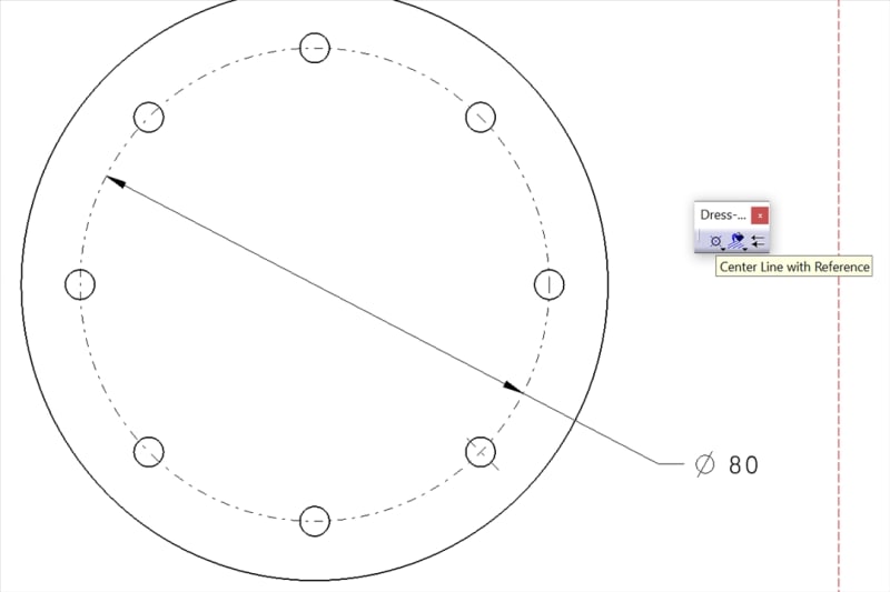
Here's my solution that's still a hack, but a slightly more robust one. Place a "centerline with reference" on one of the holes in the pattern and use a circular feature on the part that shares a center with the bolt circle as the reference. Then control click and drag one of the two endpoints aligned with the circle all the way around the bolt circle. So it will only be associative to one hole and one other circular feature (and not the whole pattern), but if you're a little smart about which hole and which feature you pick, it shouldn't matter the vast majority of the time.

Let me know if that doesn't work or you have a question. It's been a while since I've drafted in Catia, so that description is all from memory.
 
look into a view's properties, tick the option "Centerline" in Dress-up section of the View tab

regards,
LWolf
 
Select "centerline with reference" from the dress-up toolbar.
Then choose the hole as the object and then the larger diameter or a center point as the reference.
This will create a linear axis and a circular axis.
Then click on the newly formed axis, hold control key, and drag the ends of the circular axis to the extent you want.
210204_Image009_jypuq7.jpg
 
Rickyt thank you! That answers my question and creates the feature I've been attempting to do for some time. A bit of confusion at first because my centerline object already had a horizontal centerline and (as you noted) you have to drag the centerline circle around and it wasn't immediately visible. This trick will be put to good use.
 
Status
Not open for further replies.

Part and Inventory Search

Sponsor