Continue to Site

Eng-Tips is the largest engineering community on the Internet

Intelligent Work Forums for Engineering Professionals

  • Congratulations IDS on being selected by the Eng-Tips community for having the most helpful posts in the forums last week. Way to Go!

Bolt combine loading 1

Status
Not open for further replies.

DJCoutts

Marine/Ocean
Feb 25, 2016
14
Hi there

I'm currently trying to find a equation/formula to help show the applied for acting on a bolt and making sure its within the yield strength of the bolt.
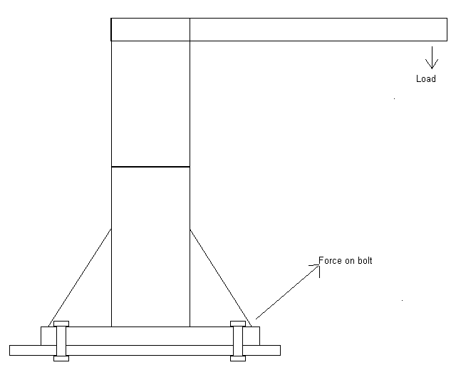
Bolt_connection_xuxvwz.png


From the image you have a davit with a load on the end, this will then transfers the force onto the bolts.

Currently i have used the shear formula and tensile to get the individual loading as followed

e.g.

Load : 6000N
Bolt : 10mm
Yield : 400MPa

Shear (single shear)

tress = Load / A..............A = 3.14 x 5^2 = 78.5398mm^2............6000 / 78.5389 = 76.3943N/mm^2 (MPa))

As there are 4 bolts holding it down then i devied the stress by the number of bolts for get the individual stress on each bolt..............76.3943 / 4 = 19.233575 MPa

400 / 19.233575 = 20.79 factor of safety (FoS)

Tensile (same formula as single shear)

Stress = Load / A..............A = 3.14 x 5^2 = 78.5398mm^2............6000 / 78.5389 = 76.3943N/mm^2 (MPa)

As there are 4 bolts holding it down then i devied the stress by the number of bolts for get the individual stress on each bolt..............76.3943 / 4 = 19.233575 MPa

400 / 19.233575 = 20.79 (FoS)

As the forces is not acting on the axis or in a shear formation but at 45Deg, do i need to have the force applied in each direct at 50%?

Also in not sure how to combine there's to get the overall stress on the bolt.

Im also aware that the load will course the davit to rotate in some wear between the base and end of the davit arm

If anyone can point me in the right direction it would be appreciated
 
Replies continue below

Recommended for you

Hi derertfox

I too what you have said and this is what i have come up with


Bolt used : 3/4 grade 5 UNC (
F: Perload force
At = As:Area of the perload
Sp: Proof load of bolt 18400 lb (c: foctor of bolt in permanent (0.89) or reuse (0.75)
Kn: Maximum minor diameter of thread (In)
Es: Minimum pitch diameter (In)
Le: Fastener length (In)
n: number of thread per inch
D: Bolt head diameter
d: hole diameter


Shear area of threads

As = π x n x Le x Kn x (1/2n + 0.57735 x (Es - Kn))

3.14 x 10 x 0.617 x 0.6552 x (1/(2x10) + 0.57735 x 0.685 - 0.6552) = 0.853514 In^2

Perload Force

F = c x At x Sp

0.75 x 0.853514 x 18400 = 11778.49 lbs

lb to N

11778.49 / 0.224808942 = 52303.36N

Clamp stress

Stress = ((π x (D/2)^2) - (π x (d/2)^2)) / F

((3.14 x (27.94/2)^2) - (3.14 x (21/2)^2)) / 52303.36 = 196.51N/mm^2

Now that i have the stress of the proof load of the bolt on the clamping area how do put this to against the plate thickness?
 
Hi DJCoutts

If the preload is 52303.36N you then divide this by the area under the bolt head - hole area, so you have the figures in the last line but you have divided the area by the force instead of the other way round.

“Do not worry about your problems with mathematics, I assure you mine are far greater.” Albert Einstein
 
Hi desertfox

I have changed it around and i now get 0.005089N/mm^2

Now im looking that is and i cant see a connection to the plate strength stopping the head/nut being pulled through.

Im either not getting it or there a part which im missing??

 
Hi

According to my calculations I get 196N/mm^2 which agrees with your figure earlier, it appears that you did the calculation correct but wrote the formula the wrong way up.
Looking at the steel plate on the website it stated a yield stress of 35ksi, now if I convert the 196 stress figure it equates to roughly 28ksi so the stress is below yield.
I want to look at the davit diagram you posted and I will comment further later on.

“Do not worry about your problems with mathematics, I assure you mine are far greater.” Albert Einstein
 
Yes sorry my bad.

I will get the drawing of the plant on Monday when I'm back in the office.

thanks again.
 
He desertfox

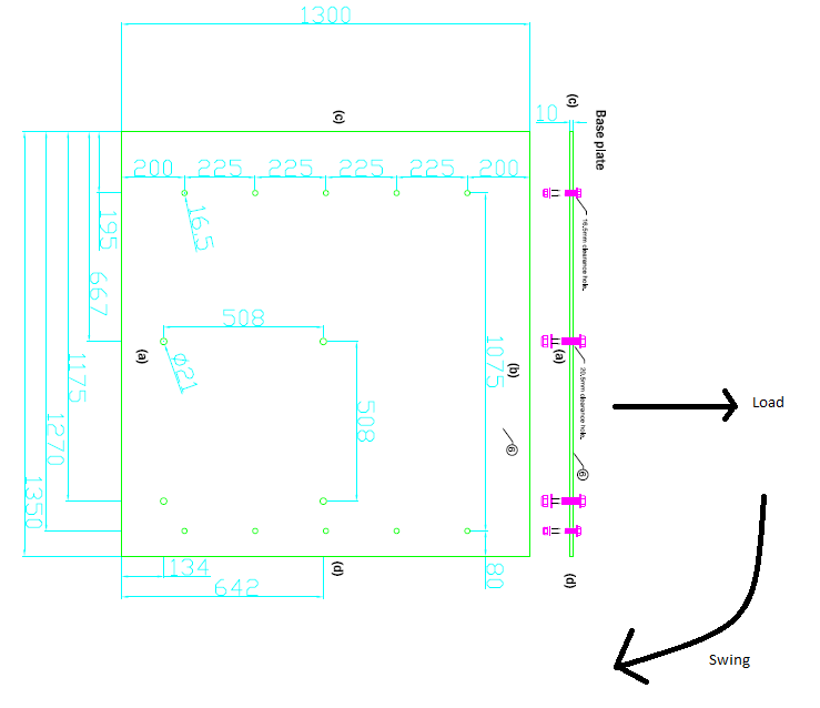
Please see the layout of the plate and retrospect to the load and swing

Plate_dimenstion_vopva6.png
 
Hi DJCoutts

How thick is the plate on the actual davit base as opposed to the one in your last post?
Also what distance have you got between the hole centres and the edge of the plate on the actual davit plate?

I think the number and size of bolts your using are okay for the lifting of the 6000N load but I want to do the calculation a slightly different way and tats why I need the dimensions.

“Do not worry about your problems with mathematics, I assure you mine are far greater.” Albert Einstein
 
Hi desertfox

I have had a look around and the manufacture of the davit don't give that information.

Here are the following for the davit base

Base size : 584.2mm square
Hole positions : 508mm square
Hole size: 20.574mm

just want to make sure that is was not miss in my earlier post, the davit it self is a off the shelf item which we have bought, so making sure that the plate we are bolting to is the right thickness will take the load with reasonable stress limits.
 
Hi DJCoutts

I think the bolts are okay given the safety factor you're using, my calculations assuming the davit plate tips at the front edge of the base plate which puts all four bolts in tension albeit that the front two bolts see only a small proportion of the load when the lift is purely vertical.
I reckon the bolts will see about 13-15kN when maximum load is vertically lifted but I haven't done any calc's when the ship rolls and the lift is no longer vertical.

“Do not worry about your problems with mathematics, I assure you mine are far greater.” Albert Einstein
 
Hi desertfox

Thanks for getting back to me on this, I think with all the calculation that have been done for the main areas where the welding and bolt connection are these will be acceptable, From this will set up a document what will go over the area which have been highlighted so that it make easier in the future do do these type of calculation.

for the bolt connection on the davit i will look more into this and get the formula for different types of bolt pattens i.e circle and squares with respect to number of bolts.

Thanks again for your help with this, certainly has jogged a few memory's of where i should be looking.

Now off to work out the weight and centre of gravity on a survey pole as it was not documented and its got to be lifted off.

Regards

Dan
 
Hi DJCoutts,

How thick is welded base flange that comes with the purchased davit/crane?
In one sketch it looks about twice as thick as the 10 mm thick base plate you are providing.
In another it is shown as about 1/3 as thick as the 10 mm base plate.

Several of the four davit flange bolts are over are 470 mm (almost 20 inches ) away from the nearest anchor bolt.
I think, when lifting 6000 N (1350 lbs) the 10 mm base plate is going to bow upward alarmingly if it is secured by the 10 bolts along the edges as shown.
 
See the OP's post dated 1st March, he states the actual load to be lifted is 600N, so at 6000N there is a SF of ten

“Do not worry about your problems with mathematics, I assure you mine are far greater.” Albert Einstein
 
Status
Not open for further replies.

Part and Inventory Search

Sponsor