Eng-Tips is the largest engineering community on the Internet

Intelligent Work Forums for Engineering Professionals

  • Congratulations waross on being selected by the Tek-Tips community for having the most helpful posts in the forums last week. Way to Go!

Bolt Fastening of Several Solid Parts with Holes

Status
Not open for further replies.

NeelArmstrong

Mechanical
Apr 3, 2023
5
0
0
US
Hello,

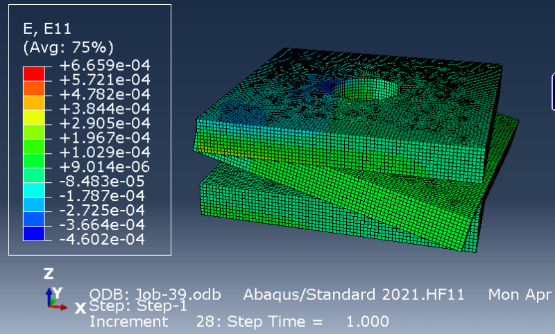
I have a composite laminate (modeled as an 18-part stack of 3d plates attached to one another via surface-to-surface ties) and separate part, all of which have connector holes (through which they are bolt-attached). I would like to use the abaqus fastener/connector capabilities to achieve the connection (rather than modeling the bolts). I have seen many examples of attaching shell components to one another, but not 3 or more solid parts. I have been trying a small-scale model (see image below) to figure how to do it but I have been having trouble.

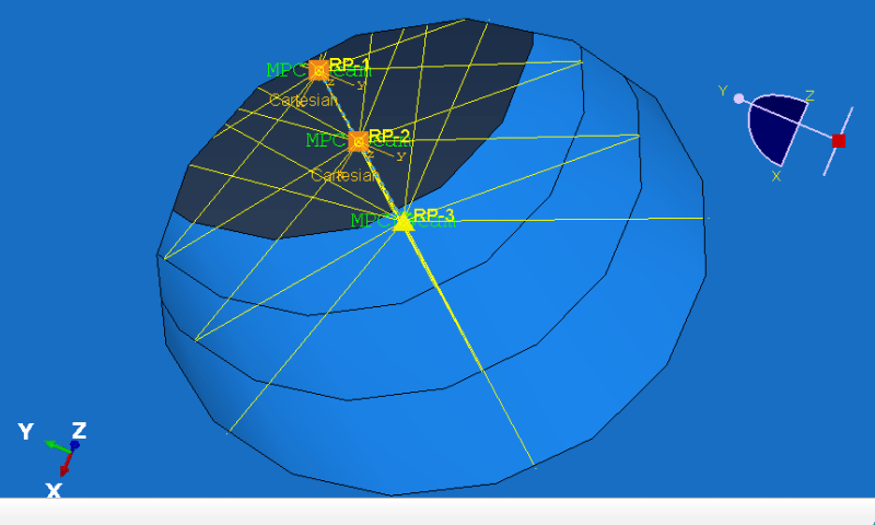
What Ive tried so far (extending an example ive seen for a shell-to-shell case): I created 1 reference point for each plate in the small-scale model (the top center of each hole), coupled the points to the corresponding circumferential surfaces (surfaces that would be in contact with the bolt shaft, attached the points via wires, and applied cartesian+align section properties to the wires. Unfortunately, the exited with convergence issues.

Does anyone have experience with this or any tips they could offer? help would be greatly appreciated.
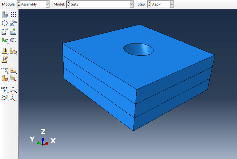
Capture_vlzoty.png
 
Replies continue below

Recommended for you

Huh, "attached the points via wires"? What specific elements did you use? if you used rigid elements, then, well, no its not realistic at all.

Why do you want/need to model the holes?
 
Check the article "Modeling Bolted Connections with Abaqus FEA" on the Simuleon blog. It discusses different approaches to bolt modeling in Abaqus. Of course, you can always use a simplified model of a bolt meshed with solid elements. However, the most common approach involves beam or connector elements representing bolt shanks, connected via coupling constraints to partitioned surfaces (representing washers) of plates being joined. For that, reference points will be needed. Beam elements might be better for a start. However, you still have to make sure that there are no rigid body motions which is often a reason of non-convergence in static analyses, especially when they involve contact.
 
FEA Way, thank you for the response. I have seen that article and I am trying to extend it to my case.

In my simple model (shown in the image above) I have the left x-surface of the top and bottom pieces disp-fixed, and the middle piece subjected to a load in the opposite direction.

Right now, I have created reference points at the absolute center of each cylindrical hole, and used MPC beams to connect those points to their curved surfaces, I used the connector builder to connect point 1 to point 2, and point 2 to point 3, and then I applied cartesian+align section to the connections (shown below). Would that be an appropriate approach? My result is shown in the second image.

Capture2_krwxkj.png


Capture3_hutm8z.png
 
SW Composites,

I have a composite plate with edge attachments to other components. I need to apply fasteners through the holes in a manner that allows me to adjust the stiffness of those fasteners.
 
Is contact defined between the plates ? It seems to be missing, based on the results. Frequency analysis may show you what else needs to be connected.
 
FEA Way,

In the image above, contact definitions were not defined. I have since added contact definitions for two surface combinations: (the bottom of plate 1 and the top of the middle plate) and (the bottom of the middle plate and the top of plate 3). In both cases, I used small sliding, surface-to-surface, with adjustment only to remove overclosure. contact interactions include tangential (frictionless) and normal (hard contact, default, no separation after contact). I also have a general contact (all and self) applied, and i fixed the y-surfaces of the middle plate from translating in the y-direction.

I think I am making progress. One big question I have .. looking at the article "Modeling Bolted Connections with Abaqus FEA" on the Simuleon blog... I am essentially trying option #2 (More accurate method for modeling bolts), but instead of two components i have 3. In my case, do I still only use beam MPC on the top-most and bottom-most points? Or do I need to use beam MPC on every layer?

Thanks again!
 
Ok, maybe, but why?: "I need to apply fasteners through the holes in a manner that allows me to adjust the stiffness of those fasteners." What structural problem are you trying to solve?

The use of MPCs (rigid elements) will give a completely wrong contact loading and local stress field. Having been down this swamp hole before, and seen others being sucked deep below the murky surface, attempting to 3D model a bolted joint connection is a complete waste of time. Its far too complex in reality - multiple contact surfaces, non-linear effects, bolt torque/clamp-up effects, friction effects, etc.

If you need a high level fastener load distribution analysis for a joint with multiple fasteners, just use a shell model with fastener elements (or beams) connecting nodes at the fastener centerlines.

 
SWComposites,

I have an assembly wherein a composite laminate is bolt-connected to other parts 21 times on two ends and 11 times on two others. In my case, I cannot use a conventional shell (because of geometric requirements), so the laminate is modeled as a stack of 3d plates that are surface tied together. stiffness-adjustable fasteners are needed because the manner of attachment used for the panel (surface ties, beams, stiffness-adjusted parameters) has had an effect on laminate stresses.
 
Those beam MPC are applied where washers would be. Coupling constraints can be used instead of them. Of course, the problem with this approach is that you can’t account for the contact between the bolt and the parts joined by it. Maybe you could try with a 3D solid model of the bolt for better accuracy. Use symmetry when possible. In some cases even threads are considered but that’s rare and usually meant for quite specific cases.
 
Hmm, the 3 plates shown in your model are 3 different parts bolted together? Or 3 plies in the laminate?

Either way, the laminate stresses from this type of model, particularly near the holes, will not be correct. What do you plan to do with the calculated stresses?
 
Status
Not open for further replies.
Back
Top