Continue to Site

Eng-Tips is the largest engineering community on the Internet

Intelligent Work Forums for Engineering Professionals

  • Congratulations KootK on being selected by the Eng-Tips community for having the most helpful posts in the forums last week. Way to Go!

Bolt in Bending Calc with Unique Geometry 1

Status
Not open for further replies.

tKc74

Mechanical
Jan 31, 2021
20
Hello, Looking for a bit of a sanity check on a bolt calculation, biggest thing is if to take the point of rotation about the bolt group centroid or the first bolt (given the geometry the first bolt could also seem like a valid option, just unsure with this geometry), calculation below shows about the centroid and seems high given configuration....again about the centroid this would be higher than about the first bolt I believe.
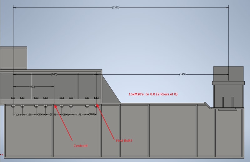
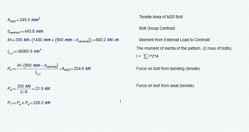
Bolt_Connection_izmuma.jpg


Bolt_Calc_wquxu3.jpg


Cheers,


“If the women don't find you handsome, they should at least find you handy.” - Red Green
 
Replies continue below

Recommended for you

Hi tKc74

I would take the moment from the far left hand of the lower beam and not the bolt centroid.
All the bolts then would share some tension from direct and bending action but the biggest load would appear in the first bolt pair and so you would size the bolts on that basis.

“Do not worry about your problems with mathematics, I assure you mine are far greater.” Albert Einstein
 
desertfox said:
I would take the moment from the far left hand of the lower beam
I agree, but I'd say from the far left bolt centre, anyway this difference is probably neglible.
 
Hi kingnero

Yes either way I agree, it just something I have always done taken the pivot to the furthest point and then assumed all the bolts are utilised and let’s face it the first pair of bolts from the left hand won’t see a great deal of tension due to bending.


“Do not worry about your problems with mathematics, I assure you mine are far greater.” Albert Einstein
 
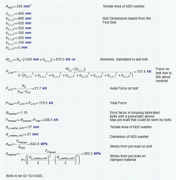
Thanks , revised the calc to pivot about the furthest bolt, updated calc below with a bit of pre-load evaluation:

BC_Rev_yethba.jpg


“If the women don't find you handsome, they should at least find you handy.” - Red Green
 
Hi tKc74

I agree with the analysis, however I think that the preload is to low, at 1.15 factor times the 179.5KN will not give sufficient margin for error on torque tightening the bolts.

“Do not worry about your problems with mathematics, I assure you mine are far greater.” Albert Einstein
 
Hi Desertfox, even with pneumatic device and lubricated bolts?

“If the women don't find you handsome, they should at least find you handy.” - Red Green
 
Hi tKc74

This link shows typical errors for tightening methods, torquing bolts is subject to +/-25% see below, to me you need to have more margin in those bolts and I have no idea whether they are seeing a cyclic load or static load, I would guess at cyclic loads if they are loading and unloading various components.


A couple of other points, at 206KN (from the previous threads on this device) preload there will be yielding of the clamped components and so you won’t achieve the preload you require. At 206KN preload if it is achievable then with a 25% error you could exceed the bolt proof load of a grade 10.9 on the other hand the preload could be 25% lower then the stated figure which means the preload would be lower than the desired calculated value of 1(79.5KN.

“Do not worry about your problems with mathematics, I assure you mine are far greater.” Albert Einstein
 
The simplified and conservative method puts the bending moment at the centroid; however, as you pointed out this isn't exactly accurate. The accurate solution is wherever the plate bending stiffness matches with the bolt tensile stiffness, force will go to each component as a function of its relative stiffness. The AISC manual Ch.7 describes this well.

“The most successful people in life are the ones who ask questions. They’re always learning. They’re always growing. They’re always pushing.” Robert Kiyosaki
 
Hi tKc74

Have a look at this link, it mentions safety factors of 1.25 to 2 but also factors of 1.1 to 1.4 if the application is tested. Scroll down to the heading AXIAL FASTENER AXIAL LOAD where you will find the S.F. mentioned.

So once you have the external load on the bolt ie 179.5KN then in my opinion that should be multiplied by at least 1.25 or whatever is suitable for your application (if you intend to load test you might be okay with 1.15) and size the bolt on that figure :- 1.25 * 179.5KN = 224.3 KN.

“Do not worry about your problems with mathematics, I assure you mine are far greater.” Albert Einstein
 
Status
Not open for further replies.

Part and Inventory Search

Sponsor