Continue to Site

Eng-Tips is the largest engineering community on the Internet

Intelligent Work Forums for Engineering Professionals

  • Congratulations cowski on being selected by the Eng-Tips community for having the most helpful posts in the forums last week. Way to Go!

Bolt Query

Status
Not open for further replies.

daparojo

Industrial
Feb 25, 2010
36

Please could you review, and see if I am going along the correct lines.

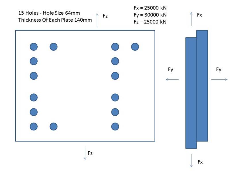
I have a plate of 15 Bolts, and is subjected to Forces in the Fx, Fz and Fy plane. The forces can only act in one direction at anyone time. See attached diagram.

The undercut of the bolt (smallest area is 57mm)i.e. area,a = 2551mm2
The Bolt diameter in hole, D = 62mm, i.e. area A = 3019mm2
Number of Bolts, N = 15

By using the formula :- F For Shear Strength Of Material
------
A N


i.e. The worse case, Fx, the Shear Strength Needed For Bolt is 220 N/mm2

My Material has a Min. Yield of 650 N/mm2 UTS 820 N/mm2
Therefore, by Shear Strength of Material is 650 x 0.57 = 370 N/mm2 - Factor Of Safety of 1.4 (370N N/mm2/261 N/mm2)

The Tensile Required For The Bolt in Fy direction. a being the undercut, smallest area.

Fy
---------
a N

Tensile Stress in Bolt is 156 N/mm2 - So pretty low compared the Yield Of Material 650 N/mm2
But also, the Round Nut and Head Of Bolt will also help to hold the joint together in Fy direction.

Now I need to calculate the Load needed to help overcome the Forces.

Load = A x Shear Stress In Bolt (Fx - is the largest force)
Load = 667 kN Clamping Load Required (A Higher Initial Is Required To Stretch Bolt)

Total Load Across Plate = 665 kN x 15 = 10000 kN which seems ok as it obviously equals Fx

Now, would the bolts fail if the Loading was the same, yet the Fx force went up to say 13000 kN which is higher than the total Load ? Yet the Bolt Shear stress would go up to say to 287 N/mm2, but the clamp load remains the same, there will be less loading in the bolts then the force. Am I correct thinking that it won't fail due to the Shear Stress in Bolt/Material Shear Stress being well within limits?


testter_u1fkhg.jpg


Many thanks
 
Replies continue below

Recommended for you

Hi
No you have to add them vectorially I will try and post later

“Do not worry about your problems with mathematics, I assure you mine are far greater.” Albert Einstein
 
no, you should not add the force components together; read my earlier post about interaction.
Fs = sqrt(Fx^2+Fz^2)
Rs = Fs/shear allowable
Rt = Fy/tension allowable

simple (conservative) interaction ...
MS = 1/(sqrt(Rs^2+Rt^2) -1

complicated interaction ...
RF^3*Rs^3 +RF^2*Rt^2 = 1, solve for RF
MS = RF-1


another day in paradise, or is paradise one day closer ?
 
Hi

Have a look at the link below


Now so questions:_

1 why are the bolts not spread evenly.

2 how frequently are the different forces applied to the plates

3 the force Fy when applied acts on the two plates, at what part does it act.

“Do not worry about your problems with mathematics, I assure you mine are far greater.” Albert Einstein
 
Cheers Fox and rb1957 for your help. I am learning very quickly thanks to your help.

Fox – the holes are spaced like that due to a cylindrical housing that will be in the middle of the plate. My task was to ignore that housing.
The working loads are a lot less than this, these loads only apply if the machine goes faulty.
The Force Fy will only act in one direction at one time i.e. not being pulled apart.

So , looking at the information from rb1957 and the link from Fox I am looking the Combined Shear and Tension failure.

Using:-

(V/Vsd)^2+(Te/Tnd)^2 <=1.0

V= Applied Shear = 1250 kN (Fz or Fx / No Bolts)
Vsd = Design Shear = 1684 kN (0.57 * Material Yield * Shear Area Of Bolt, A)
Te = External Tension = 1500 kN (At Working Tension Not Applied Tension Load)
Tnd = Design Tension Capacity = 2500 kN (Yield Of Material * smallest area i.e. undercut, a)
A = 3019 mm2
a = 2551 mm2

The answer = 0.933
I am I on the correct lines?

 
Ho daparojo

Well it looks okay to me, not sure why I thought the clamped plates were only 10mm thick, I thought I'd seen that figure in an earlier post, anyway the reason I asked about the bolt positions is that because the bolt pattern is not symmetrical it might lead to unequal tension forces in the bolts I.e. Force in Fy direction.
Can you provide more detail of how the cylinder fits on the plate and why these forces only come about if the machine goes faulty.

Incidentally do you not have anyone you can ask at your works about this?

“Do not worry about your problems with mathematics, I assure you mine are far greater.” Albert Einstein
 
"V= Applied Shear = 1250 kN (Fz or Fx / No Bolts)" ... no! you have two components of shear, not the larger of the two.

I've showed you how to combine these components, and if you don't know how to, well, you should !

with only a 3% margin, this difference is probably enough to make it "NFG", or just No Good.

another day in paradise, or is paradise one day closer ?
 
Hi rb1957

I think looking at the original post that their is only one component of shear,Fz and Fx appear to have the same direction even though Fz is of the opposite sign, I took it that either Fz or Fx could occur but not both at the same time, maybe the op can clarify.

“Do not worry about your problems with mathematics, I assure you mine are far greater.” Albert Einstein
 
he defines three forces acting on the bolt group.

another day in paradise, or is paradise one day closer ?
 
Yes rb1957 but if you look at the diagram they are in the same plane and Fz is given as negative, I expected Fz,Fx,and Fy to act perpendicular to each other.

“Do not worry about your problems with mathematics, I assure you mine are far greater.” Albert Einstein
 
sorry Fz shouldn't be a negative.

Only one force will acting at anyone time.

Rb1957,I'm sorry if I don't fully understand the way to combine the two forces, as I have said, I'm trying to educate myself along the way.

Please enlighten me where I have gone wrong with my figures as I thought I had finally got my head around the problem.
 
"Only one force will acting at anyone time" ... we're used to important details being left out.

"Fz shouldn't be a negative" ... no matter, +ve or -ve shear have the same effect (only acting in different directions.

if only one in-plane force acting at a time, then using the larger one is correct.

sorry, but we expect a certain level of engineering knowledge here (this is meant to be a professional site), vector combining of components is below that level.

out of curiousity, how do you have only one shear direction active at a time ? the shear goes from X to zero to Z ?

another day in paradise, or is paradise one day closer ?
 
Hi daparojo

Can you provide some answers to my earlier post about how the cylinder is mounted on the plate because the bolt pattern is asymmetrical which means the assumption that all the bolts share equal tensile load might not be valid.
Also does the Fy force should it be present try to separate the two plates or compress them together.

“Do not worry about your problems with mathematics, I assure you mine are far greater.” Albert Einstein
 
I did put on my opening thread about only one force actions at anyone time.

I will post details about the housing later today.
 
"I did put on my opening thread about only one force actions at anyone time." ... my apologies, I didn't read carefully enough.

if you really mean only one force at a time then there's no interaction.

or did you mean only one shear at a time, applied in conjunction with the tension ?

I'd still be interested in how the load changes ?


another day in paradise, or is paradise one day closer ?
 
RB1957
Thank you for your help.
I take it by if you really mean only one force at a time then there's no interaction then the vector doesn't apply - only if say Fx and FY were at the same time?

The Forces only act at anyone time, not in combination.

Hypothetically, what would happen if the nuts were just hand tight and the Force went in the Fx direction? With the material able to stand the Shear force, the tension doesn't need to be considered. With it being tensioned it would lower the shear force due to the plates being clamped.

Apparently the housing in semi circular and is fixed via fabrication and other bolting. At this stage we know very little and told that we didn't need to consider it whilst looking at this solution. The bolt pattern is something we don't have control on, only the size and number of bolts. It's been pretty sketchy at times.

Thank you for you help to Fox and RB1957, it's been invaluable, and personally I've learned a lot through your help.

 
if you mean only one in-plane force combined with out-of-plane Fy then there is interaction, as I've described; but the single in-plane force simplifies it to RF^3*Rs^3+RF^2*Rt^2 = 1.

thinking about your stresses I think you should look at
1) the tension stress (only) at the min. area, and
2) the combined stress (tension and shear) on the shank area.
I wouldn't combine tension stress based on minimum area with shear stress based on shank area.

another day in paradise, or is paradise one day closer ?
 
Hi daparojo

Your welcome that's what the site is here for to help people.

My only concerns are from your description of the joint because I'm not sure how Fy separates the plates under faulty conditions, or with the preload on the bolt whether or not you are embedding the nut/bolt head into the clamped material and finally to mention the bolt pattern being asymmetrical which might well mean unequal tensile forces in the bolt, we appear not to check any of these conditions which personally I think should be checked.

“Do not worry about your problems with mathematics, I assure you mine are far greater.” Albert Einstein
 
Status
Not open for further replies.

Part and Inventory Search

Sponsor