Continue to Site

Eng-Tips is the largest engineering community on the Internet

Intelligent Work Forums for Engineering Professionals

  • Congratulations waross on being selected by the Eng-Tips community for having the most helpful posts in the forums last week. Way to Go!

Bolted blind flange design with multiple opening as per ASME 3

Status
Not open for further replies.

Vishal Mistry

Mechanical
Apr 25, 2018
8
IN
Hello all,

I want to discuss regarding the design of blind flange with multiple opening on it. I have designed the blind flange as per ASME SEC VIII div I Appendix-2 and for multiple opening, I have also verified the flange as per UG-39(d)(2) and (e)(1).

Flange OD = 1100mm

Flange Thk. = 80mm

The blind flange has Dia.45mm 24 Nos. openings and 5Nos. Nozzles are mounting on it. Refer below sketch for your reference. Nozzle N1,N3,N2,N4 are 2"NPS and Nozzle N11 is 3" NPS. Refer below drawing.
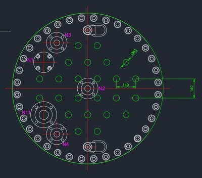
Blind_flange_top_view_9FDA920E-BFFE-9507-66D569F64E340DD2_ip1cyh.jpg


Please provide your suggestion on this.

Thanks & Regards,
Vishal Mistry
 
Replies continue below

Recommended for you

Suggestions with respect to what exactly? Im not sure if I understand your question.
You mentioned;
The blind flange has Dia.45mm 24 Nos. openings and 5Nos. Nozzles are mounting on
Are the green circles through thickness openings in the blind, with no nozzle, 24 in total? What are the openings for?
 
It looks like a blind flange cover in the end of the pipe, which has multiple openings and nozzles. IMO, these openings and nozzles may be evenly spaced apart on the blind flange for better flow distribution and less stress concentrated on one side.
 
To me it seems that you have got it right with ASME VIII Div-1. Blind flange shall follow rules in UG-34 and Apx 2. When there are multiple openings over it you also have to apply UG-39. It is a complex calculation but this is the end of the story.
 
Thank you Vikko for your opinion.

The blind flange has 24 Nos. x dia.45 hole on it. Which is shown in the drawing with green color and 5 nozzles are mounting on it which is mentioned in my first post.
 
I still dont seem to understand (and may be the only one) what the green holes are for. What is mounted on or to them, when you also have noles with nozzles? Or are the holes female threaded in some way? Or will a pipe be inserted and welded to the flange? Not sure how youre hoing the create a differential pressure ..
 
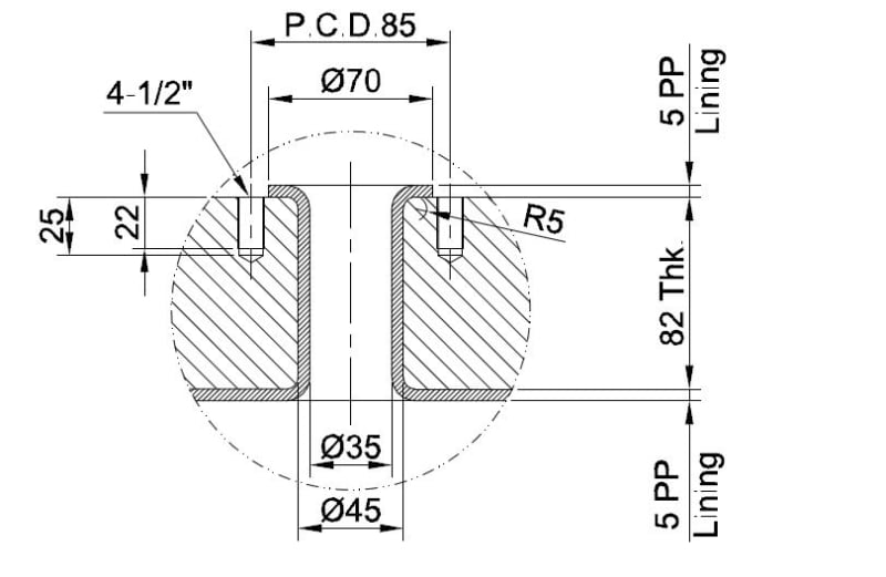
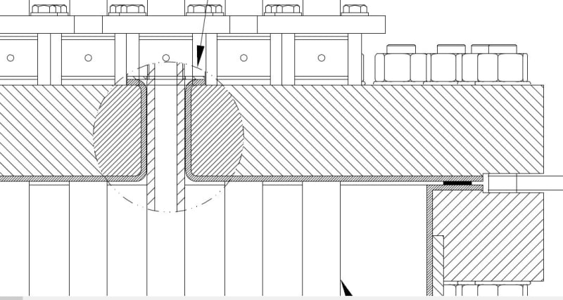
the candles are mounted through this holes. Pressure is not acting inside the hole. Refer below section sketch for the hole.

Capture_wfb5lb.jpg

1234_ffvjk6.jpg


I hope now this is clear.
 
It looks like a simple case of following the code rules.
What is your question?
If you are not confident of the design and don't know what questions to ask in this forum to become confident in your design, then perhaps it would be wise for your employer to find someone else to design this equipment.
 
I am pretty sure about this design. I have already verified the flange as per the ASME SEV VIII Div I Appendix 2, UG 34 and UG 39. I have posted this thread in a forum because of the discussion. I am not asking any question. Here you can provide your suggestion regarding the design as per the ASME code.
 
Perhaps ASME VIII-1 Appendix 41 might provide some further guidance with respect to the multiple penetrations without consideration of any "nozzle neck".
 
Spot on Tom, App 41 is an appendix often forgotten while it provides great use for certain designs. However, I never have found a section in App 41 saying whether the heating elements may be (aprtially) hollow. Section 41-6(a) seems to implicitly say that it does not affect the design or calculation.
 
I believe appendix 41 (formerly a code case) is only really applicable to EIH support plates, and this design with the additional nozzles around the outside doesn't meet the conditions of applicability either.

Unlike a tubesheet with some possible level of tube joint enhancement, the ligament efficiency in the EIH support plate calculation does not allow for any contribution of the tube wall, therefore it doesn't matter if the heating element was solid or hollow.
 
From being "pretty sure" about your design, with the input from the complete strangers in this forum, what level of confidence do you now have that your design is safe? Would your confidence now exceed "I am moderately confident"?
 
Because I found my thinking and other thinking are almost matching. That's why now I am more confident with my design.
 
Status
Not open for further replies.

Part and Inventory Search

Sponsor

Top