Continue to Site

Eng-Tips is the largest engineering community on the Internet

Intelligent Work Forums for Engineering Professionals

  • Congratulations waross on being selected by the Eng-Tips community for having the most helpful posts in the forums last week. Way to Go!

Bolted connection for a beam in bending 12

Status
Not open for further replies.

HanStrulo

Civil/Environmental
Apr 16, 2021
117
Happy Monday everyone,

I have a new challenge and I am not sure how to approach it.
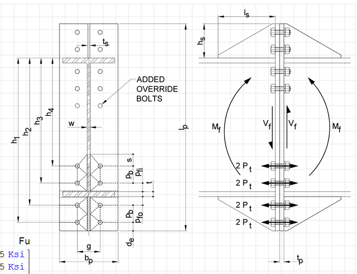
I have a beam in classic bending (max bending at the middle) and I want to install it using bolts.
The beam will come in two sections that i have to join in the middle( where the max moment is). I have never done a bolted connected design for anything other than tension and shear and I have no idea how to approach this challenge.

Any methodology? references? examples?

Thank you
 
Replies continue below

Recommended for you

Brad805,

I didn't have any problems using a 1.75" distance to the HSS wall. Usually I do a minimum edge distance of 2" to accommodate most market accessible wrenches, but I had VERY tight architectural clearances on this job for cladding, glass, etc. So I decided to go with 1.75". It was also nice because the prying action check cut 0.25" off of the required plate thickness, and there were hundreds of these connections. So I decided to save some plate. And yes, nothing goes out unchecked where I work. I verified the erectors could get a wrench on it by inserting a "gun" block in AutoCAD.

Gun_fit_yxixqh.png
 
"but the idea here is to prefabricate the the beam and the support and bolt it in the middle at site."

Is this normal practice (for you guys) ? I understand there is some gain in pre-fab but it constrains the middle of the beam. In this case I would not use a tension bolt joint (due to the difficulty in ensuring the two faces align). I'd use shear splice on the outer surface or the inner surface. Are you constrained with the envelope ? Can you use the outer surface for your splice ?

another day in paradise, or is paradise one day closer ?
 
@rb1957

This is not a normal practice. More of a suggestion to reduce work at site. I don't even know how much more expensive it will be to go from regular welding of beams to the supports to prefabricated systems that will be bolted.

With the idea of bolting the beams at the location where moment is maximum, i assume I will end up with alot of bolts and plates to make the connection work. I am not even sure if it's worth it but i am pushed to try to reduce time and investigate easy assembly options.

For your second question, there are no space constraints, so i could use splices anywhere.

Thanks
 
A W24x104 would be on the smaller side for a bridge girder, but easily within the applicable range for the AASHTO method, and it's a fairly straightforward design and fabrication, consisting of a total of 8 plates (only 3 different sizes for a symmetrical section) and bolts. The AASHTO LRFD 7th edition and later specs utilize a simplified method that's much easier than what was in the older specs.

Bolted Field Splices for Steel Bridge Flexural Members


Rod Smith, P.E., The artist formerly known as HotRod10
 
@Brad805, AISC provides entering and tightening clearances required for different size bolts in table 7-15 of the steel construction manual. For a 1"Ø bolt it is listed as 1-3/8". I regularly use 1-1/2" and have never had an issue made of it from the field.
 
If I was doing it, I'd attach (maybe temporarily) the splice plate to one 1/2, to help align the 1/2s at the splice.

another day in paradise, or is paradise one day closer ?
 
HanStrulo said:
i assume I will end up with alot of bolts and plates to make the connection work.

I ran it through our splice design program with roughly the loads you mentioned (except I used a much smaller shear value, assuming the 1300 KN was the max shear, which wouldn't be at midspan). A graphic of my results is attached (just for an approximation, of course). Bolts are 7/8" HS (A325); girder and splice plates are A36.


Rod Smith, P.E., The artist formerly known as HotRod10
 
 https://files.engineering.com/getfile.aspx?folder=5b4cb7ba-1a05-4789-9b7e-dc77c55edaec&file=w24x104.PNG
DrZ, thank you. Nothing you have ever posted suggests you might be the type not to check things. Dauwerda, thank you. I think I will finally buy the AISC guides and code. I am in Canada and I do not do a ton of steel connection design.
 
@ BridgeSmith
Thank you. when i do a manual check, i will compare it to your results.

Can I ask what program is that?
 
It's a pretty massive connection... see attached 8 bolts bot + 10 bolts top... 1" dia, and 1" end plates. Weld is 1/2" Fillet all around... see attached; please check prior to using. I'll run the weld through my other program. Took longer because I had to modify my 4+4 Bolt program. The 3/8" thick end plate stiffener has to be increased to 1/2"

Rather than think climate change and the corona virus as science, think of it as the wrath of God. Feel any better?

-Dik
 
 https://files.engineering.com/getfile.aspx?folder=cd65b33c-ca82-4769-b94b-72b817f22807&file=Eng.pdf
Can I ask what program is that?

Looks like BRASS-SPLICE from WY DOT

Yes, that's correct.

Rod Smith, P.E., The artist formerly known as HotRod10
 
why not a shear splice ? ... splice plates on the flanges with fasteners in shear, rather than an end-plate and fasteners in tension ?

another day in paradise, or is paradise one day closer ?
 
The 800 kN-m moment was a 'tip off'...

Rather than think climate change and the corona virus as science, think of it as the wrath of God. Feel any better?

-Dik
 
@ dik

Thank you for the massive amount of details. some checks i did not even know existed. I will check it before using it of course.

Can the connection work without any welds? I am trying desperately to avoid welding.


Yes... it can work as the detail the DrZ noted, but for those loads you will have a handful of bolts and then some... Welding can be done in the shop, where it is also less costly. I suspect the welded end plate connection will be the least costly. Bolts loaded in tension are the most efficient. Note that the fasteners used are 1" dia... I've updated the program to show the stiffener plate dimensions.

image_nrqn47.png


Rather than think climate change and the corona virus as science, think of it as the wrath of God. Feel any better?

-Dik
 
I suspect the welded end plate connection will be the least costly.

My suspicion would be that the bolted field splice typically used for bridge girders would be the more economical. as I said, that W shape would be on the lighter side for a bridge girder, but is sometimes used.

The other advantage to the splice with flange and web plates is that it allows for adjustment at erection to get the in-place alignment right.

Rod Smith, P.E., The artist formerly known as HotRod10
 
I often use a shim (thickness not spec'd) to allow for fitup during erection

Rather than think climate change and the corona virus as science, think of it as the wrath of God. Feel any better?

-Dik
 
Status
Not open for further replies.

Part and Inventory Search

Sponsor