Magos
Mechanical
- May 3, 2023
- 5
Hello all!
I have a couple of issues regarding the FEA analysis of a bolted connection and I was hoping you could help out. This is my first time posting so please let me know if this is the right place or if my post lacks information.
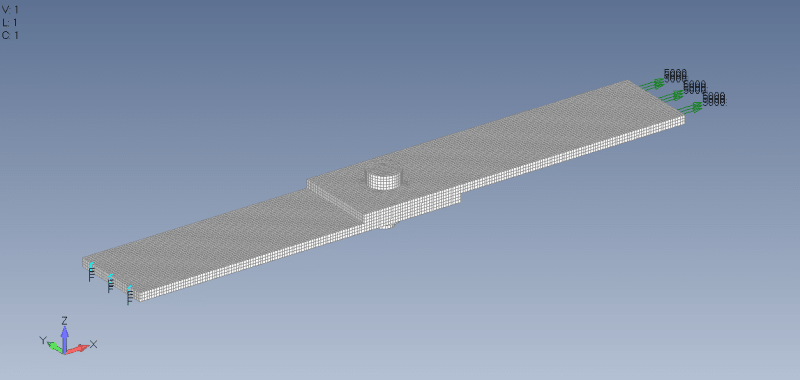
I've been recently tasked with validating the design of an assembly that includes bolted connections. As it isn't something I've done before, I decided to start simple by following the this guide (Link). Here's a picture of the assembly. I've also attached the .modfem files.

The most relevant parameters are as follows:
[ul]
[li]Plates are 200x50x5 mm[/li]
[li]Connection is done via M12 bolt and nut [/li]
[li]Material is 1020 carbon steel for all elements, imported directly from the software database[/li]
[li]The assembly is loaded with 5000 N in the X+ direction at one end and fixed in place at the other[/li]
[li]Meshing is done with a hexahedral elements with size set at 1.5 mm [/li]
[li]Bolt is meshed as it's done in the guide: by removing a section in the middle, creating two RBE2 elements and linking them with a bar element[/li]
[li]Bolt preload is 10 kN (Arbitrary)[/li]
[li]Contact connection (Frictionless) between the two plates. Default settings except for the contact iterations being raised[/li]
[li]Glue connection between the bolt head and the area where it touches the plate. Same for the nut. Default settings [/li]
[/ul]
My issues start with that last glue condition. While not explicitly stated, I assume that the guide defined all surface to surface connections as contact conditions that prevent solid penetration while allowing sliding. The problem is that when I did that the model ended up not being completely constrained, with the normal modes analysis showing that the parts were free to move everywhere. I was only able to solve this by applying that glue connection between the bolt head/nut and the plate. This obviously isn't a good representation of reality.
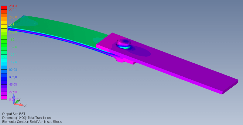
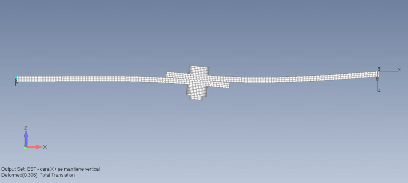
Moving on, once I perform the static analysis (SOL 101) the results just don't look right. First, only one of the plates is bending. While I understand the results won't be exactly symmetrical given the boundary conditions, shouldn't there be at least some bending in the second plate?
Second, I checked the axial force in the bar element using List>Output>Query and it outputs 9393.154 N. Shouldn't this be at least 10 000 N given the specified pre load?

Thank you for your time. I hope that with your help I'll be able to model a bolted connection that actually reflects reality.
I have a couple of issues regarding the FEA analysis of a bolted connection and I was hoping you could help out. This is my first time posting so please let me know if this is the right place or if my post lacks information.
I've been recently tasked with validating the design of an assembly that includes bolted connections. As it isn't something I've done before, I decided to start simple by following the this guide (Link). Here's a picture of the assembly. I've also attached the .modfem files.

The most relevant parameters are as follows:
[ul]
[li]Plates are 200x50x5 mm[/li]
[li]Connection is done via M12 bolt and nut [/li]
[li]Material is 1020 carbon steel for all elements, imported directly from the software database[/li]
[li]The assembly is loaded with 5000 N in the X+ direction at one end and fixed in place at the other[/li]
[li]Meshing is done with a hexahedral elements with size set at 1.5 mm [/li]
[li]Bolt is meshed as it's done in the guide: by removing a section in the middle, creating two RBE2 elements and linking them with a bar element[/li]
[li]Bolt preload is 10 kN (Arbitrary)[/li]
[li]Contact connection (Frictionless) between the two plates. Default settings except for the contact iterations being raised[/li]
[li]Glue connection between the bolt head and the area where it touches the plate. Same for the nut. Default settings [/li]
[/ul]
My issues start with that last glue condition. While not explicitly stated, I assume that the guide defined all surface to surface connections as contact conditions that prevent solid penetration while allowing sliding. The problem is that when I did that the model ended up not being completely constrained, with the normal modes analysis showing that the parts were free to move everywhere. I was only able to solve this by applying that glue connection between the bolt head/nut and the plate. This obviously isn't a good representation of reality.
Moving on, once I perform the static analysis (SOL 101) the results just don't look right. First, only one of the plates is bending. While I understand the results won't be exactly symmetrical given the boundary conditions, shouldn't there be at least some bending in the second plate?
Second, I checked the axial force in the bar element using List>Output>Query and it outputs 9393.154 N. Shouldn't this be at least 10 000 N given the specified pre load?

Thank you for your time. I hope that with your help I'll be able to model a bolted connection that actually reflects reality.

