Christian S said:
BAretired; thank you for your answer, but I'm confused. Are you saying the tensile forces have no effect on the end plate?
No, that would be wrong. There are several tensile forces acting on the plate. Any one of these can produce bending moment and shear on the plate.
But here is what you said in your original post:
Christian S said:
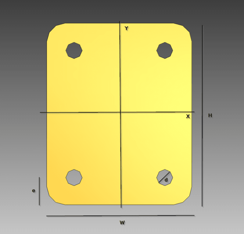
I have a bolted endplate with a connected SHS to it, and I want to find the total tensile force on this plate. The obvious one is the applied Fz component, but I guess I need to consider the tensile force from Mx and My as well (see attached picture). Can you give me some tips on how to find the total tensile force?
If the plate is in equilibrium, the total force and total moment
on the plate in any direction is zero.
Fz is the axial force delivered by the HSS. If it is downward, anchor bolts are not involved because the plate simply bears against the substrate, which acts upward. Together, they cause moments in the plate, but the resultant upward force on the plate is zero.
If Fz is upward, the HSS is in tension and Fz is resisted by four anchor bolts, which cause moments and shear in the plate, but again, the total tensile force on the plate is zero.
Moment Mx produces tension 'T' on two anchor bolts and compression 'C' on the opposite edge of the plate. We know that T = C and Mx = T/d (or C/d) where d is the effective distance between T and C. T acts at the center of bolts, but the precise position of C is not known. If we assume that d = 0.9(H-E), then the two anchor bolts create a moment about the face of the HSS tending to bend the plate down. On the opposite edge, force C tends to push the plate up.
A similar argument can be made for My. Plate moments for Fz, Mx and My can then be determined, approximately by adding the three effects together algebraically.