Continue to Site

Eng-Tips is the largest engineering community on the Internet

Intelligent Work Forums for Engineering Professionals

  • Congratulations KootK on being selected by the Eng-Tips community for having the most helpful posts in the forums last week. Way to Go!

Bolted endplate connection, total tensile force

Status
Not open for further replies.

Christian_S

Mechanical
Oct 31, 2022
23
Hey

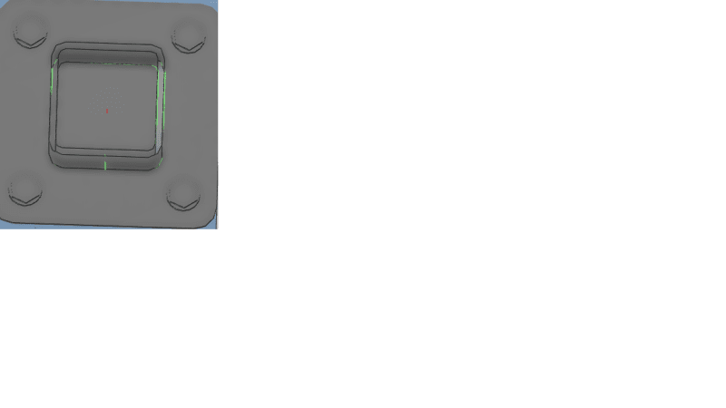
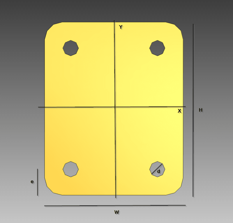
I have a bolted endplate with a connected SHS to it, and I want to find the total tensile force on this plate. The obvious one is the applied Fz component, but I guess I need to consider the tensile force from Mx and My as well (see attached picture). Can you give me some tips on how to find the total tensile force?
endPlate_yte8ug.png
 
Replies continue below

Recommended for you

Student question? This is awfully simple, assuming we're talking about a rigid plate. Tensile force in a plate seems a weird ask however
 
do you mean the total force applied to the plate (how would we know from the information given), or
the total force the plate can react (similarly, not enough information).

agree with above ...

"Hoffen wir mal, dass alles gut geht !"
General Paulus, Nov 1942, outside Stalingrad after the launch of Operation Uranus.
 
Can be caused by Mzx, Mzy, or Tzz.

-----*****-----
So strange to see the singularity approaching while the entire planet is rapidly turning into a hellscape. -John Coates

-Dik
 
EDIT: Please ignore this post as it is incorrect. See following post.

Plate tension = Fz + Mx/d[sub]1[/sub] + My/d[sub]2[/sub] where d1 = h - k.e and d2 = w - k.e
The value of k is approximately 1.1.
 
to be fair the OP is asking for "tension load". Sure, he may mean "tension stress" ... but words have meaning.

"Hoffen wir mal, dass alles gut geht !"
General Paulus, Nov 1942, outside Stalingrad after the launch of Operation Uranus.
 
rb1957 said:
to be fair the OP is asking for "tension load". Sure, he may mean "tension stress" ... but words have meaning.

The expression I gave was intended to be for tension load, but I think I made a mistake.

If the HSS has a tension of Fz, tension on each bolt would be Fz/4, for a total of Fz for 4 bolts and zero for the plate.
Mx would add a tension of Mx/d1 to 2 bolts and a compression of Mx/d1 to the plate.
My would add a tension of My/d2 to 2 bolts and a compression of My/d2 to the plate.

d1 and d2 are the effective depth in the x and y direction respectively. d1 is about 0.9(h-e). d2 is about 0.9(w-e).

So the total compression force felt by the plate would be Mx/d1+My/d2. The plate would feel no tension force because tension is always carried by anchor bolts.
 
mea culpa ... I read the moment terms as Mc/I ... but you mean the couple, (My)/d ... but then the net force is zero ...


"Hoffen wir mal, dass alles gut geht !"
General Paulus, Nov 1942, outside Stalingrad after the launch of Operation Uranus.
 
rb1957 said:
... but then the net force is zero ...

The net force of a couple is zero, but only half of each couple is taken by the plate; the other half is taken by two anchor bolts, so the plate resists a net compression and zero tension.
 
Sorry, the explanation was sparse for this problem. The thing is I'm making a program that checks bolted connections with end plates like in the picture with SHS beams connected to them. Users can input Fx, Fy, Fz, Mx, My and Mz (according to the axis in the picture) together with dimensions for the endplate and the SHS. I've programmed all checks for the bolts, so now I'm programming the checks for the endplate.
I've found the design tension resistance according to EC3 1-8 table 6.2, but I was unsure what the actual tensile forces on the plates were given the parameters mentioned above.
 
perhaps your question is more like "what checks should I do in an end pad ?"

"Hoffen wir mal, dass alles gut geht !"
General Paulus, Nov 1942, outside Stalingrad after the launch of Operation Uranus.
 
That might be a question for later yes, the point of this thread was to get the total tensile force acting on the plate so I could calculate the utilization ratio.

BAretired; thank you for your answer, but I'm confused. Are you saying the tensile forces have no effect on the end plate?

Maybe it didn't come through earlier, but the HSS is connected at the centerpoint like this.

Untitled_w6bxxa.png
 
is "utilization ratio" the same as "reserve factor" (= Allowable/Applied) ?

Is it something important to you guys ?

The total "tension" (ie out-of-plane) load that can be applied is limited by ...
1) the tension capacity of the fasteners, [1]
2) the tension capacity of the central tube (taking load away from the plate),
3) the compression capacity of the central tube,
4) the shear capacity of the plate around the central tube,
5) the shear capacity of the plate around the fasteners,
6) the flange bending of the plate (as load is carried between the fasteners and the central tube), and
7) a bunch of things I haven't thought of.

[1] The summed tension capacity of the fasteners could easily be misleading, in that loading (ie moments) can overload an individual fastener.

"Hoffen wir mal, dass alles gut geht !"
General Paulus, Nov 1942, outside Stalingrad after the launch of Operation Uranus.
 
Christian S said:
BAretired; thank you for your answer, but I'm confused. Are you saying the tensile forces have no effect on the end plate?

No, that would be wrong. There are several tensile forces acting on the plate. Any one of these can produce bending moment and shear on the plate.

But here is what you said in your original post:
Christian S said:
I have a bolted endplate with a connected SHS to it, and I want to find the total tensile force on this plate. The obvious one is the applied Fz component, but I guess I need to consider the tensile force from Mx and My as well (see attached picture). Can you give me some tips on how to find the total tensile force?

If the plate is in equilibrium, the total force and total moment on the plate in any direction is zero.

Fz is the axial force delivered by the HSS. If it is downward, anchor bolts are not involved because the plate simply bears against the substrate, which acts upward. Together, they cause moments in the plate, but the resultant upward force on the plate is zero.

If Fz is upward, the HSS is in tension and Fz is resisted by four anchor bolts, which cause moments and shear in the plate, but again, the total tensile force on the plate is zero.

Moment Mx produces tension 'T' on two anchor bolts and compression 'C' on the opposite edge of the plate. We know that T = C and Mx = T/d (or C/d) where d is the effective distance between T and C. T acts at the center of bolts, but the precise position of C is not known. If we assume that d = 0.9(H-E), then the two anchor bolts create a moment about the face of the HSS tending to bend the plate down. On the opposite edge, force C tends to push the plate up.

A similar argument can be made for My. Plate moments for Fz, Mx and My can then be determined, approximately by adding the three effects together algebraically.
 
rb1957 said:
is "utilization ratio" the same as "reserve factor" (= Allowable/Applied) ?

Is it something important to you guys ?

Yes, it's the same. It's important in the sense that we want the program/GUI to show all relevant reserve factors for the connection.

To me it seems like number 6 is the case that fits our scenario.

 
If leveling nuts are used under the base-plate, anchor bolts can take compression as well as tension. In that case, why not consider the area and moment of inertia of the bolt group, then calculate the force in each bolt? From that information, calculate the maximum base-plate moment required.

If leveling nuts are not used, the above method should provide a conservative estimate of the required base-plate moment.
 
I have trouble seeing how this can be critical to a design ? "Surely" something else would be critical ?? for example an individual fastener load ? how do you make "total load" sensitive to moments ?

"Hoffen wir mal, dass alles gut geht !"
General Paulus, Nov 1942, outside Stalingrad after the launch of Operation Uranus.
 
rb1957 said:
I have trouble seeing how this can be critical to a design ? "Surely" something else would be critical ?? for example an individual fastener load ? how do you make "total load" sensitive to moments ?

Not quite sure what you mean by your last question, but if the HSS is a small profile compared to the plate height and width this could be critical?
 
you ask about "total load on the plate". a moment does not change the total load. BA suggests maybe looking at the load on 1/2 the plate, to capture the couple ... but that's not your "total load".

yes, of course the HSS (tube?) could be critical, and sensitive to moments. my point 2 (back on the 1st) is something like this. There I talk to total load in the tube, but local stress is more critical.

"Hoffen wir mal, dass alles gut geht !"
General Paulus, Nov 1942, outside Stalingrad after the launch of Operation Uranus.
 
Status
Not open for further replies.

Part and Inventory Search

Sponsor