Eng-Tips is the largest engineering community on the Internet

Intelligent Work Forums for Engineering Professionals

  • Congratulations waross on being selected by the Tek-Tips community for having the most helpful posts in the forums last week. Way to Go!

Bolted Web Connections 1

Status
Not open for further replies.

Engineer John

Structural
Jun 2, 2023
7
0
0
US
Steel beams that are only bolted through the web are traditionally designed assuming they are pinned supports. If the connection were only say 4 bolts (2x2), any engineer would assume a pinned connection. However, say the beam is deep and there are a significant amount of bolts. Say a 2x10 bolt configuration. A bolted connection that deep would be able to resist some moment. So the question is: How many bolts can there be in a shear connection. before one can no longer consider it pinned? When can a large bolted connection be considered as a fixed support? Is there any guidance from any know sources regarding this?
 
Replies continue below

Recommended for you

You might consider reading of AISC 360-16 Section 10,11, and 12.

AISC States. "While simple shear connections do actually posses some rotational restraint, this small amount can be connected and the connection idealized as completely flexible.

A quick review of Table 10-1 should indicate that even more lots of bolts, connections can still be idealized as a pin.

There are several factors of the bolted connection that contribute to it's relative rotational flexibility. Some important ones are, bolt slip prior to bearing, reduced cross section at the bolted connection interface.

Basically if your not grabbing on to the flanges of the WF beam, your never going to approach a fully restrained connection because for it to be fully restrained you need to develop the stiffness of each connected cross section at the joint.
 
"Bolt plowing" is another one. In the web, at ultimate loads prior to failure, the bolts will be able to plow through the web as you get localized plastification and allow it to rotate.

And, if you assume that it is pinned, the required section will be stiffer and limit the end rotation even at high loads.
 
I did look at the AISC Steel Manual. My connection most closely matches that of a Single-Plate Connection with extended configuration. Table 10-10 really only addresses a single line of bolts. I do understand that the connection cannot be considered as purely fixed. But a large bolted connection could still take some moment. If I were to use modeling software such as SAP2000, I considered assigning a rotational stiffness to the ends of the member. However, it seems there are no design guides to assist with a assigning a rotational spring constant (K).

 
Difficult to do by hand. If you really want to look at it that closely, a Component-Based FEM might be a good route. IdeaStatica is a really powerful connection design software that will calculate rotational stiffness of your joint.
 
It would be very unconventional to use a shear plate connector for any kind of moment resistance. I think it would be a poor decision to rely on any moment restraint of such a connection for lateral resistance or stability.

 
Calculating the moment capacity of the connection is fairly straightforward. For connections with fully-tensioned bolts in a slip-critical connection, the slip force can be quantified, and combined with the polar moment of inertia of the bolt group, the moment a first slip can be calculated. Quantifying the stiffness of a connection where the bolts are not tensioned would be fairly futile, since you'd have to assume it's zero, until the bolts come into bearing against the sides of the holes. Then it's all metal deformation until you reach the limit of bolt shear capacity or tearout of holes.
 
Engineer John said:
How many bolts can there be in a shear connection before one can no longer consider it pinned?
When can a large bolted connection be considered as a fixed support?

IMHO, never, because it's a matter of scale...
A 2x2 connection is used on what these days... maybe a W12, maximum?
A 2x10 connection on a W36?

Load carried by a W36 with that connection are not even in the same league with a W12.

I've used 2x10 connections on heavy W36s. A project with W36s, with 2x10 connections, carrying the largest/heaviest railroad locomotives made, pulling a unit train of coal cars loaded to the max across a coal unloading pit at one of our electric generating stations. While on the beams, the train is stopped and external vibrators shake the dickens out of each coal car to make sure it is unloaded.

No way I would to cut corners and assume even partially fixed connections.

I'm sure there are many other uses for 2x10 (or other "large" connections) that are not as demanding, but the basic principal is the same... heavy loads, or a "large" connection would not have been used.

 
OP - is your question to try to reduce a beam size (bad idea), or to better understand the system and potential moment transfer to weaker members like a relatively slender column (good idea)?
 
Say the beam is modeled with fixed ends; if the slip capacity of the bolt group is greater than the applied service moment, could the connection be modeled as fixed? On the other hand, if the moment applied is greater than the bolt group capacity, should the model be changed to assume pinned connections?
 
For partially restrained moment connections AISC Says the following: "The AISC Specification requires that the structural engineer have a reliable moment-rotation curve before design can proceed."

Further it says: "When used, the analytical model of the PR connection must include the force-deformation characteristics of the specific connection."

If you look at the example PR moment connections in AISC, they are all going to be considerably more rigid than a flange plate with bolts, and yet they are still considered partially restrained.

This is raises a big red flag regarding your approach. The difficulty in developing a proper force-deformaiton curve, combined with the relatively small gain seems like this is not a good idea for sizing the beam for strength/deflection like Pham mentions.

If your trying to get less beam, or justify an existing connection using this philosophy I think its a bad idea. But you haven't really explained why you want to do this so we can only speculate.

 
if the beam is modelled with fixed ends, well in that case there should be gussets joining the caps to transfer the moment.

but the fully fixed end is the worst case for the structure (locally), so the moment will create a set of out-of-plane loads on the webs (in the absence of the cap gussets) which you'll need to apply to the web. how to analyze ? IDK, maybe the shear capacity of some circle of web material around the fastener ?

but pinned ends are the worst case for the beam; you can release the ends, apply the end moments to the span of the beam superimpose the beam loading, and that's pretty close to what'll happen is you model it.

"Hoffen wir mal, dass alles gut geht !"
General Paulus, Nov 1942, outside Stalingrad after the launch of Operation Uranus.
 
Based on the above responses, it appears that more knowledge about the behavior of the joint is needed before any attempt can be made to model it as partially restrained. It also appears there are no publications available that can easily allow a designer to assign a rotational spring coefficient. Therefore, convention is to pick either a pinned or fixed condition based on the connection type and design for that. (Pinned for a web only connection, and fixed if the flanges are engaged.)

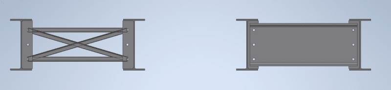
The member in question is a welded steel plate diaphragm for a bridge. The bridge is very wide with variable loading across it. The 3D bridge model resulted in high axial forces in the diaphragm regardless of the beam end fixity conditions assumed. The girders and diaphragms are modeled as beam elements and the deck as plates. We initially modeled the diaphragms with pinned ends, but there has been much back and forth whether that was a correct assumption.

The number of bolts required to resist axial loads resulted in a 2x11 bolt pattern. Which again, can take considerable moment. However, if the diaphragm is modeled with fully restrained ends, then the bolt group will fail. Whether we should attempt to design for that kind of moment was still in question. We threw around ideas of spring constants, moment reduction factors, and modeling the ends of the beams with less stiffness; all in attempt to reduce the end moments. I feel after reading many of your responses that our initial assumption to model the diaphragms with a pinned end was valid. But I am open to any other input from this forum. Thank you.
 
"in a 2x11 bolt pattern. Which again, can take considerable moment" ... sure, but what is the impact of these out-of-plane loads on the web ?

one way (not that I'm recommending it) to "push" the joint to react like a pinned would be to concentrate the fasteners ... instead of a tall 2*11 pattern, what about a 4*6 pattern ?

I'm not familiar with your terms ... is the "diaphragm" the deck ? should it be "fully constrained" ? does this mean a row of nodes with 6 dof constrained ? if so, I doubt this is good modelling ... but hopefully (surely ?) more knowledgeable folks will join in. If the bridge is a deck supported by beams, then I'm surprised the constraint of the deck means much. Is it constrained in moment ? It is probably constrained axially (along the bridge) and maybe vertical (out-of-plane of the deck); but across the bridge I'd rather see a finite (rather than an infinite) stiffness.

"Hoffen wir mal, dass alles gut geht !"
General Paulus, Nov 1942, outside Stalingrad after the launch of Operation Uranus.
 
So, is the connection under consideration between the connection plate at the girder and the end of the diaphragm, or a connection in the middle of the diaphragm?
 
I would think you'd have to model it as fixed for the Service II load combination, with limits based on the capacity of the connections at first slip of the slip critical connections. That may control the number of bolts required, instead of strength. If it doesn't, trying to design it for a partially fixed condition gets very complicated, because then you have limited movement of the connection at loading between the first slip and when the bolts come into bearing against the sides of the holes. However, the amount of movement to get there requires an assumption of where the bolts were aligned in the holes before they slipped into bearing.

That's too complicated, with too many assumptions for me. If the diaphragms are included in the structural model, I would just assume the connections as fixed, and provide the number of bolts required for that condition.

If you don't have room for the number of bolts required, consider reducing the (actual) stiffness of the diaphragms to reduce the loads on the connections.
 
Why would you consider a web only connection fixed? Is it because it is a slip critical connection? Are you suggesting that all slip critical connections need to be designed for moment?
 
Until it slips, even a web-only connection with fully tensioned bolts is fixed.

Before slip, the only flexibility in the connection, is the elastic or plastic deformation capacity of the connected members.
 
Yes. as BridgeSmith says plenty of 'pinned' connections may behave as rigid connections. And they might even do so for their entire service life!

IMO if there is ever any doubt your structure and its members should be analyses for the behaviour of pinned AND rigid connections. Though in VAST MAJORITY of cases, assuming pinned is a more conservative choice so for the structure. It is not uncommon for me I to pick both rigid and pinned behaviour and model them. This is particularly true for nominally pinned base plates, which in most cases behave very much like a rigid connection. It should be noted that occasionally a pinned joint REALLY is needed and then careful detailing might be required.

In most cases such as the one describers, where a pinned style connection is behaving rigidly and attracts too much moment and 'fails' then really as long as the transition from rigid to pinned is smooth and ductile then there really isn't an issue.

In reality this is where we need to turn our engineering head on an make some intelligent decisions. For the case of LTB I often consider a web cleat as rigid. Eg consider the two examples below:

Untitled_cbnss8.png


The one on the left we would normally consider as pinned connections but behave structurally as a rigid cross braced frame. In contrast the example on the right we would normally consider as pinned and the channel gives no rotational restraint to the I-beams. This is clearly inconsistent thinking.

For the purposes of LTB, I consider the connection on the right to be rigid.
 
Status
Not open for further replies.
Back
Top