Continue to Site

Eng-Tips is the largest engineering community on the Internet

Intelligent Work Forums for Engineering Professionals

  • Congratulations waross on being selected by the Eng-Tips community for having the most helpful posts in the forums last week. Way to Go!

Bolts and T-Stubs and Prying, Oh My! 2

human909

Structural
Mar 19, 2018
2,036
I hope the title caught you attention, and I hope you are enthused to have your thinking caps on.

So we as good engineers know that, we should use thick/(or gusseted) plates when we are designing connections with significant tension loads. A big part of this is so we can use a rigid plate approach and simplify connection design and reduce prying forces on our bolts.

But what about when we don't have a rigid connection under tension? What do we want to accept as satisfactory?
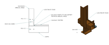
Exhibit A:
1738231879704-jpeg.4174


This is the bottom chord and walkway of a 20m truss gantry. This is a very ugly connection under tension as it is the bottom chord.

The bottom chord is HSS(125x125mm) and the verticals are 125x10Angle. 2xM24 bolts above and below the HSS chord. It is pretty clear that the 10mm plate section of the angle isn't stiff enough for the load here. (At a guess 25mm plate would be better)

This deflection is under dead weight only (which is about 80% of service load and 40% of ultimate load.) Bolts even with prying are more than satisfactory and the plate is unlikely to fail (I have yet to explicitly calc this out). How would you deal with this situation? Would you reject it? Perform significant rectification? Accept it if it calcs out?

Any thoughts appreciated.
 

Attachments

  • 1738231879704.jpeg
    1738231879704.jpeg
    301.4 KB · Views: 425
Replies continue below

Recommended for you

Oh and this isn't just one isolated join. There are several. Here is one with a larger gap. Including some minor weld cracking where the stress has been concentrated closest to the bolts.

1738232757632.png
 
Potential design issues aside, were the bolts properly pre-tensioned as they should be for this type of joint? It doesn't look like they were. I can see a gap between the plates at the bolt line. For that gap to develop at a pre-tensioned bolt there should have to be severe strain on the bolt. Maybe it is just the picture, but I would question the bolt installation. If this is recently erected, are there any visible marks that would indicate the bolts were pre-tensioned using a the turn-of-nut method?
 
If there is weld cracking (albeit minor) at 40% of ultimate loads, would this not be quite a severe cause for concern as fracture of the weld would be a brittle failure of the gantry?
 
Is it possible this is due to fabrication and fit up issues rather than flexural yielding of the plate? Only one side of the connection appears to have rotated.

Either way, if the numbers show that the first hinge at the HSS yield under dead load only I would certainly call for remediation. A 1/4" deflection is a common deformation limit for these connections, this Bo Dowswell paper is a good reference from AISC: https://ej.aisc.org/index.php/engj/article/view/1009/1008
 
How are the legs of the angles welded to the 'other" side of the HSS?

I wonder if "they" make them like that any more.

The late, great Omer Blodgett on "load path" -

Are you considering a restorative repair, or instead a modification to mitigate and stabilize the joints against the day next month the men's club is scheduled to tour the facility?
 
I also would be concerned about the weld fractures; could result in brittle type failure.

I would design a heavy "bathtub" type fitting to fit inside the area below the fasteners extending up beyond where the fasteners are, remove the fasteners, weld in the fitting all around, reinstall longer fasteners.
 
Another thing. There are a dozen joints similar to this. The one shown is one of the worse ones.

Potential design issues aside, were the bolts properly pre-tensioned as they should be for this type of joint? It doesn't look like they were. I can see a gap between the plates at the bolt line. For that gap to develop at a pre-tensioned bolt there should have to be severe strain on the bolt. Maybe it is just the picture, but I would question the bolt installation. If this is recently erected, are there any visible marks that would indicate the bolts were pre-tensioned using a the turn-of-nut method?
Good pickup and I picked up the same thing and observably worse in other joints. And the answer is a definitive no. There has definately been site assembly shortcomings as well as engineering shortcomings here.

For the joint that I supplied the photo for, I asked one of the workman to fully tension the bolt. When he started to do (I was not present), when he observed the local weld crack and stopped pending further advice.

In ANOTHER location, where the forces and prying was lower, the bolt was extremely under tightened and I could see plenty of daylight through at the bolt shank. I got the torque wrench onto this bolt before I tightened it and the bolt was approximately at 15% of required tension based of torque measurements which aren't an exact science in the field but give a approximate indication.

If there is weld cracking (albeit minor) at 40% of ultimate loads, would this not be quite a severe cause for concern as fracture of the weld would be a brittle failure of the gantry?
There is a HEAP of weld in there. So fracture at one location does not mean that there is a lack of capacity. The full amount of weld is ~3x what is required at ultimate capacity. So a tiny weld failure at one point does not necessarily mean it is understrength as a localised crack causes the load to be redistributed in a more favourable manner.

HOWEVER. I do think that the the most likely failure mode would be progressive weld cracking in a zippering type fashion. If the plate is bending to the degree it is, then the stresses get concentrated on the closest welds. If they crack the they get concentrated on the next welds in line and so on until failure. Additionally truss has equipment on it that will have regular (but not severe) vibration. So yes, this is a pertinent issue.

Is it possible this is due to fabrication and fit up issues rather than flexural yielding of the plate? Only one side of the connection appears to have rotated.

Either way, if the numbers show that the first hinge at the HSS yield under dead load only I would certainly call for remediation. A 1/4" deflection is a common deformation limit for these connections, this Bo Dowswell paper is a good reference from AISC: https://ej.aisc.org/index.php/engj/article/view/1009/1008
Both fabrication and fit up is far less than perfect. However there are several connection like this and the plates are definitely insufficient for the job. Thans for the link to the paper. I'll have a look.

Your mention a maximum deflection figure is the first I've seen, thanks. I've seen this issue before in similar circumstances, but of a magnitude closer to 1mm than 10mm.

How are the legs of the angles welded to the 'other" side of the HSS?
A general weld all round connection. So a heap of weld. But some of it is 20mm from the bolted connections, other welds are 150mm. The load path isn't consistent or direct.
 
I would design a heavy "bathtub" type fitting to fit inside the area below the fasteners extending up beyond where the fasteners are, remove the fasteners, weld in the fitting all around, reinstall longer fasteners.
That is approximately where my mind was going regarding a proper restoration.

Though I was thinking we need to directly engage the chords further back from the join, use long threaded rod to tension the chord together then perform the restorative work at the connection. It will involve a decent amount of work across several joints. But if it is required then it needs to happen.

For those wondering:

This is not my design.
 
Last edited:
Weld cracking
1738258211926.png

There is at least 750mm of weld in this joint due to the manner it has been detailed and constructed. The that crack there is a failure of 10mm so around 1%. But again the bigger question is more what is going to occur over time.

Here is a sketch.

1738259857983.png

As you can see due to the overlapping components (kick plate, verticals, channel underneath) there is not a even weld load path for the tension from the HSS chord to the bolts. An ugly configuration.

And the discussion so far has been mostly looking at the top as that is more accessible. The bottom is likely a greater concern due to the thin 6mm unstiffened web.

EDIT: I've done some extremely preliminary analysis of the channel. And I very much don't like it.**

** That is an understatement and I don't see how this design can be justified. Further discussions with the involved parties will be had.
 

Attachments

  • 1738261845092.png
    1738261845092.png
    59.7 KB · Views: 12
Last edited:
Seems like if you design up some sort of "fixes" that you are then going to own this mess. So I would be very conservative in the analysis and fix design, particularly if there are any safety implications of a failure.
 
Seems like if you design up some sort of "fixes" that you are then going to own this mess. So I would be very conservative in the analysis and fix design, particularly if there are any safety implications of a failure.
Thanks for your advice. And that is the conclusion that I have now come to in the last hour.

My preferred course of action is to let the original engineer propose a fix for the mess. But if I am not satisfied I'll get an external peer review. I am the guy in the middle advising the D&C firm, but I think I'll leave solutions for this one to others.

For what it is worth. There is a fair bit of engineering design on this site that I did perform and I do own. That was the reason why I was on site and how I encountered this mess.
 
Last edited:
Why is the plate bending? Actual tension forces? Or just due to fit up?
 
Why is the plate bending? Actual tension forces? Or just due to fit up?
Absolutely due to tension forces. Likely in the order of 100-150kN... (I haven't modelled this structure myself at this stage.)
 
With the joints opening, is there much corresponding excess truss deflection?
 
This seems like a good application for Idea Statica to determine the stiffness of these joints. The plates seem thinner than even what I see in a PEB joint.

I doubt anyone would have thought this was your design. You do not give the vibe you miss much.
 
With the joints opening, is there much corresponding excess truss deflection?
Not really. Or at least none that I could eye-ball. There are only a few joins per span and generally only one that displaying considerable opening.

Overall from deflection and serviceability perspective the trusses affected by this issue seem stiff and suitable for purpose. In terms of member sizing the truss seems conservatively designed for the loads. (Though I haven't crunched the numbers on this truss). For context, I did personally design a similar truss on this site which is around 30% lighter chord size despite having a slightly longer span. The tension connection had symmetric bolted 20mm plates with the bolts as close to the chords as practicable. They performing as expected as 'rigid' plates, no visible deformation.

I have no concern about the members, just the connection. The load path is convoluted and the plates that are bolted together are relatively thin.


This seems like a good application for Idea Statica to determine the stiffness of these joints. The plates seem thinner than even what I see in a PEB joint.
I agree IdeaStatic is a wonderful tool. But the number of members intersecting here and the location of the welds would really make a complete model difficult. Honestly, at this stage the stiffness of the joint doesn't concern me. The ultimate strength and the ultimate strength over time (fatigue) is what grabs my attention. As alluded to above, my position on solving this problem has change from my first post. I consider this not my problem to solve. But I will watch closely to ensure that it is solved suitably.

I doubt anyone would have thought this was your design. You do not give the vibe you miss much.
Thank you sir. 🫡

(Though part of me always want me to do better. This design was accessible for me to review well before it went into fabrication or was erected. So maybe I could have caught it... But I am yet one engineer and I can't do or analyse every design.)
 
Last edited:
True. None of this is complicated to model in Tekla, and from that you can direct link to IDEAStatic with the Checkbot easily. Modeling this in Tekla is easy. One creates a few custom components, and you are off to the races. Since it is not your problem to fix, it seems the problem stops for you at the report stage.
 
True. None of this is complicated to model in Tekla, and from that you can direct link to IDEAStatic with the Checkbot easily. Modeling this in Tekla is easy. One creates a few custom components, and you are off to the races.
Thanks. Maybe I need to catch up to the 21st century. I have yet to acquire a full IDEAStatica license. But I think that is only a matter of time. I've trailed the program and I love it. And I don't mind leaning heavily on FEA and other sophisticated tools as long as I stay grounded in the real world.

Since it is not your problem to fix, it seems the problem stops for you at the report stage.
I'll do my best to achieve this. But likely due to my heavy involvement with the principle D&C contractor the problem will remain within my oversight, if not my direct responsibility.

But I/we will sort it out. Better to catch the issue now than have it fatiguing for a few years and then a disaster later.......
 
I have no concern about the members, just the connection
Looks like some strap plates are needed, positioned like your tape measure.
 

Part and Inventory Search

Sponsor