Continue to Site

Eng-Tips is the largest engineering community on the Internet

Intelligent Work Forums for Engineering Professionals

  • Congratulations waross on being selected by the Eng-Tips community for having the most helpful posts in the forums last week. Way to Go!

Bolts and T-Stubs and Prying, Oh My! 2

human909

Structural
Mar 19, 2018
2,036
I hope the title caught you attention, and I hope you are enthused to have your thinking caps on.

So we as good engineers know that, we should use thick/(or gusseted) plates when we are designing connections with significant tension loads. A big part of this is so we can use a rigid plate approach and simplify connection design and reduce prying forces on our bolts.

But what about when we don't have a rigid connection under tension? What do we want to accept as satisfactory?

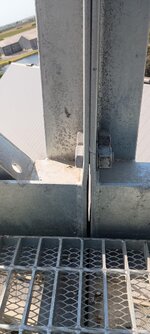
Exhibit A:
1738231879704-jpeg.4174


This is the bottom chord and walkway of a 20m truss gantry. This is a very ugly connection under tension as it is the bottom chord.

The bottom chord is HSS(125x125mm) and the verticals are 125x10Angle. 2xM24 bolts above and below the HSS chord. It is pretty clear that the 10mm plate section of the angle isn't stiff enough for the load here. (At a guess 25mm plate would be better)

This deflection is under dead weight only (which is about 80% of service load and 40% of ultimate load.) Bolts even with prying are more than satisfactory and the plate is unlikely to fail (I have yet to explicitly calc this out). How would you deal with this situation? Would you reject it? Perform significant rectification? Accept it if it calcs out?

Any thoughts appreciated.
 

Attachments

  • 1738231879704.jpeg
    1738231879704.jpeg
    301.4 KB · Views: 425
Replies continue below

Recommended for you

Looks like some strap plates are needed, positioned like your tape measure.
Great idea. I was already thinking welded plates. But you description of 'strap plates' made me think of a bolted approach. Either blind bolts into the HSS or through bolts picking up plates either side.

As mentioned above. I'm passing the responsibility for the design of this to those originally responsible. But that doesn't prevent me from nudging them in a particular direction. ;)

(Bolting strap plate will mean backing off the bolts in the original connection to transfer the load. But I don't see an issue there...)
 
Bolting strap plate will mean backing off the bolts in the original connection to transfer the load. But I don't see an issue there...)

The only potential issue I see is that it might open slightly more before the bolts engage. In these situations, minimal bolt clearance is highly beneficial. There's no need for the standard 2mm oversized holes. You can clamp the plates on, drill the holes with the mag drill, and thread the bolt straight in.

Welding works too, and avoid all the issues of bolting, except then you're welding gal steel. Not necessarily the end of the world...
 
Haven't read all replies. Would quote limit on Ze from commentary to avoid service load yielding. Extend principle here. Doesn't meet code intent. Recommend fixing but owner decision if only serviceability problem.
 
I'm a semi-regular user of IDEA Statica. I don't think this would be overly difficult to model. I don't think an FEA model would tell you anything you don't already know about this connection.

This connection detail sucks. Pure speculation here, but it seems to me this is a "pre-designed" modular component from the manufacturer. In my experience, these items have potential to be poorly designed, or not designed at all. The detail is great from a fabrication perspective as they're using the vertical member as connection material for the chord. But now if the end plate thickness doesn't work you either need to add another component to the connection or increase the thickness of the entire vertical member. Same idea with the channel splice at the bottom.

The 6mm channel web has no business acting as an end plate transferring any considerable amount of load. Especially with the bolts that far from the chord. It shouldn't take FEA or even a calculator to determine that this isn't a good idea. See above comment about poor design work, or complete lack of design.

I think Tomfh is right with the strap plates. If this thing doesn't need to move anytime soon I'd be looking at welded reinforcing. I'd also discount any strength provided by the existing detail - those are erection bolts now.
 
The only reason to look at FEA would be to prove to those who will incorrectly suggest this is a fit up problem before they agree to fix the problem. It would also be interesting to see the effect on the webs if you have a lot of stretched connections along the length of the chords. Beyond that, the problem is obvious as suggested.
 
Thanks all. Some great and helpful replies here. We all seem to be on the same page.

I'm a semi-regular user of IDEA Statica. I don't think this would be overly difficult to model. I don't think an FEA model would tell you anything you don't already know about this connection.
Agreed. For interest I did a quick FEA of the model as I have the 3D available. No consideration of the welds just a fully homogenous piece. And it revealed nothing surprising. A struggling PFC, that is saved somewhat by the stiffness of the vertical angles.

This connection detail sucks. Pure speculation here, but it seems to me this is a "pre-designed" modular component from the manufacturer. In my experience, these items have potential to be poorly designed, or not designed at all. The detail is great from a fabrication perspective as they're using the vertical member as connection material for the chord. But now if the end plate thickness doesn't work you either need to add another component to the connection or increase the thickness of the entire vertical member. Same idea with the channel splice at the bottom.

The 6mm channel web has no business acting as an end plate transferring any considerable amount of load. Especially with the bolts that far from the chord. It shouldn't take FEA or even a calculator to determine that this isn't a good idea. See above comment about poor design work, or complete lack of design.
This was an engineered item. However it did take a previous poor design (that has been in place for a decade or so) and designed a new truss with loads on it with poorer detailing. The result is what we see.

I think Tomfh is right with the strap plates. If this thing doesn't need to move anytime soon I'd be looking at welded reinforcing. I'd also discount any strength provided by the existing detail - those are erection bolts now.
Agree.
 

Part and Inventory Search

Sponsor