sleepdrifter
Mechanical
- Mar 21, 2025
- 10
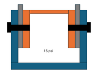
I'm designing a part that will attach to a circumferential bolt pattern, with threaded holes on the mating component. In my attached picture below, the blue components is my part that will have thru holes, the orange component is the mating component with threaded holes, and the grey component will be shims I use to occupy the .020" gap I'm leaving to put the joint into friction. The mated assembly will be sealed and pressurized to 15 psi.
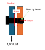
My primary question is, can I just use a simple bolted joint shear calculation on this? I was referencing Bolted Joint Analysis 4th addition, section 19 for joints loaded in shear. And using a grade 8 3/8-24 fastener and the pressurized diameter being 10.7 inches, I got a decimal when solving for the number of bolts I needed to withstand a force of 1348.8 lbf. I know it's not a massive force but I feel that my calculations are off. Can someone help point me in the right direction of how I can solve for number of bolts needed considering my joint? I believe I oversimplified the calculations.
My primary question is, can I just use a simple bolted joint shear calculation on this? I was referencing Bolted Joint Analysis 4th addition, section 19 for joints loaded in shear. And using a grade 8 3/8-24 fastener and the pressurized diameter being 10.7 inches, I got a decimal when solving for the number of bolts I needed to withstand a force of 1348.8 lbf. I know it's not a massive force but I feel that my calculations are off. Can someone help point me in the right direction of how I can solve for number of bolts needed considering my joint? I believe I oversimplified the calculations.
")