Continue to Site

Eng-Tips is the largest engineering community on the Internet

Intelligent Work Forums for Engineering Professionals

  • Congratulations waross on being selected by the Eng-Tips community for having the most helpful posts in the forums last week. Way to Go!

Bond beam interupted by W-shape bearing on shear wall

Status
Not open for further replies.

BButler505

Structural
Feb 27, 2015
15
Ok, so I'm looking for some details of how to transfer the forces in a bond beam that is disrupted by a W-shape beam at a reentrant corner. I have attached a crude drawing to show my situation. The bond beam that is parallel to the W-shape I'm going to weld rebar to the beam web and tension splice within the bond beam. I'm not sure how to make the connection with the bond beam perpendicular to the beam web though. Thanks
 
 http://files.engineering.com/getfile.aspx?folder=464a1aea-848a-4791-9d0f-482b7d3bbee8&file=Drawing1.pdf
Replies continue below

Recommended for you

BButler505 said:
I'm not sure how to make the connection with the bond beam perpendicular to the beam web though. Thanks

Before we dive into it in earnest, what are the sources of the forces that you mean to transfer with this connection? I only ask because, frankly, I'm surprised that such a connection would be required. And, of course, the best possible answer would be that no connection is required at all.

BButler505 said:
The bond beam that is parallel to the W-shape I'm going to weld rebar to the beam web and tension splice within the bond beam.

I remember this from the other thread! Sweet detail. I still have a couple of concerns however.

1) I worry about the constructability of the welded joint between rebar and beam. It looks as though it would require the rebar to be cast into the bond beam such that it would be perfectly centered on the beam web. I'd recommend something that accommodates some misalignment tolerance.

2) Looking at the connection, it appears that it will create an unintended moment connection between your beam and your wall. There could be a few remedies for that:

a) drop the bond beam down a course.
b) don't make the welds until all dead loads are in place.
c) provide a nice stiff beam to limit end rotation.

I like to debate structural engineering theory -- a lot. If I challenge you on something, know that I'm doing so because I respect your opinion enough to either change it or adopt it.
 
I think the best idea would be koot's option a. drop the reinforced bond beam 1 course and turn it into a psuedo 2 block beam. Discontinuous horizontal rebar in the top layer (I'd be specifying knock-out blocks), continuous reinforcement in the bottom bond beam, single legged stirrups at some spacing to tie it all together.
 
I found a detail I may use just have to crunch the numbers. The forces in the bond beam are from metal roof decking acting as the diaphragm from wind/seismic/blast loading. So I need the bond beam to be continuous, or at least transfer the force as though it were continuous. The W16X31 is relatively stiff, only two k-series joists are bearing on it with trib. width of about 15' with 6' spans on the joists.
 
 http://files.engineering.com/getfile.aspx?folder=4642ed50-83ea-49a0-8821-e39d5e69d5bd&file=Figure_7F.1.pdf
Also, the reason for the welding and splicing of rebar to the web of the beam is because this beam serves as a shear collector within my diaphragm.
 
I'm fairly certain that you need no connection perpendicular to the beam web BButler. Your chords need to be continuous to the corner but not around the corner. Know that I'm trying to be helpful here, not argumentative.

Shame on the concrete masonry folks. That ill-conceived bond beam "lap splice" looks to be nearly worthless. Whoever came up with it clearly isn't a concrete designer on the side.

I like to debate structural engineering theory -- a lot. If I challenge you on something, know that I'm doing so because I respect your opinion enough to either change it or adopt it.
 
Yea def. not concrete designers. I do need the connection to the beam web with the bond beam that is parallel to the W-shape to drag the shear into the shear wall. But, I'm going to use the concrete masonry association detail (with some adjustments for splice length and such) to bypass the W shape around the reentrant corner and transition to a bond beam lower in the wall and then transition back up to the normal bond beam elevation
 
The simplest detail would be to drill a couple of holes through the beam web and thread corner bars to match the bond beam reinforcement through each hole.

BA
 
I have a couple other thoughts on the preliminary detail (I am guessing this is a work in progress and this stuff will probably be considered latter)

Is A307 rebar available anywhere?
Suggest drawing the embed plate and beam to scale (W16x31 has 5 1/2 wide flange, plate looks closer to 4"x6" and only one headed stud is shown).
Suggest adding stiffener plates to the beam at the support.
 
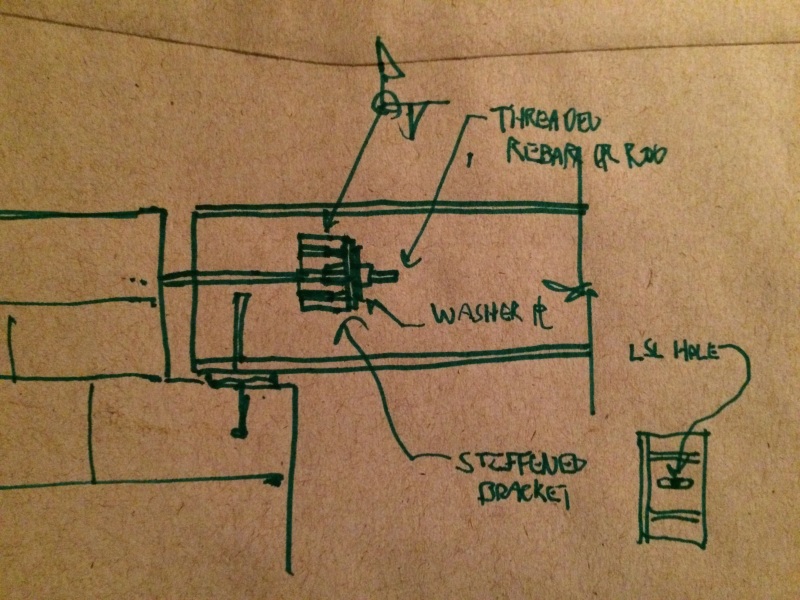
The sketch below is my attempt to introduce some misalignment tolerance into the connection. Originally, I was thinking that the wall had to be constructed before the beam arrived on site in which case tolerances would be important. Now I'm questioning that assumption. Maybe it is reasonable to assume that the beam will be in place when the bond beam is being constructed. I figured I'd post the detail regardless as I've already drawn it.

Will the load path for drag strut compression need to run through the extended bond beam rebar as well?

image_sbhiiu.jpg


I like to debate structural engineering theory -- a lot. If I challenge you on something, know that I'm doing so because I respect your opinion enough to either change it or adopt it.
 
KootK,
No, fortunately this is an addition to the existing fire station and there are high bay walls that block wind loading from introducing compression into the drag strut (W shape). Seismic loading could introduce compression into the member, but this is in a relatively low seismic zone and the geotech report seems to indicate we have pretty decent soils.
 
Status
Not open for further replies.

Part and Inventory Search

Sponsor