Continue to Site

Eng-Tips is the largest engineering community on the Internet

Intelligent Work Forums for Engineering Professionals

  • Congratulations KootK on being selected by the Eng-Tips community for having the most helpful posts in the forums last week. Way to Go!

Boost Engine with a heat recovery system - Nat. Gas Compression 1

Status
Not open for further replies.

Pulsater555

Petroleum
Sep 30, 2019
11
Hello All,

I am currently looking at an application where we want to boost an engine to provide more horse power to a compressor. The engine type would either be a Waukesha or a CAT natural gas engine for compression applications, exp: 7044GSI or 3512. This application would only be used when the compressor frame can take more horse power than what the engine can normally provide.

The waste heat recovery system will be able to provide an additional 100hp. The idea is to tie the motor to the cooler jack shaft and feed the power back into the engine thus providing more power for the compressor to utilize.

What are the communities thoughts on a configuration like this? Has a system like this been tried before?
We are imagining that a system like this would be similar to an electrically assisted bicycle in the sense that the electric motor can kick in to help the bicycler while peddling.
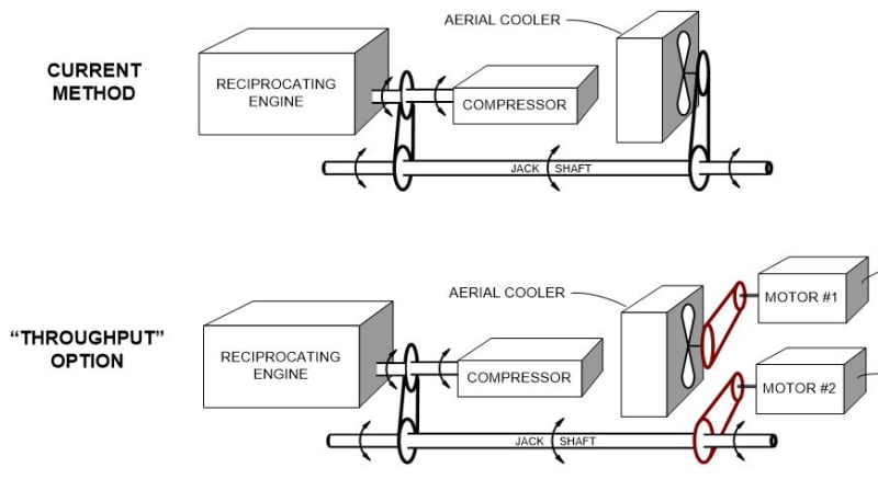
Capture_wwmhxk.jpg
 
Replies continue below

Recommended for you

You are describing a turbocompound. Typically, it is not practicable to simply add a power turbine to the exhaust of an existing turbocharged engine. Generally, it is necessary to rematch the boost turbocharger and retune engine parameters such as valve lift curves and ignition timing to reach a worthwhile result.
At any rate, the power turbine will tend to be large and expensive, as will the power train to deliver the turbocompound shaft power at a useful rpm.

"Schiefgehen wird, was schiefgehen kann" - das Murphygesetz
 
The waste heat recovery idea has been tried by multiple entities, mostly in Europe, at least on CAT engine based, cost and complexity made the attempts I'm aware impractical.

Even in cogeneration applications with modern gas engines utilizing waste heat to drive an auxiliary generator haven't seemed to be feasible for a number of reasons.

Depending on where you're at in the world it will also be difficult to "retune" the engine and install a different turbo since engine ratings are regulated for emissions, and changes like that could require extensive remapping of engine ECM controls.

If you're thinking about doing this on older series engines in non-regulated areas, then you may see some benefit. We did a project in Western Australia several years ago on using waste heat recovery to provide additional power capacity for both electric set generators and large industrial engines driving large hydraulic power systems for mine operations, there was marginal gains in that system mainly due to high delivered fuel costs to the site.

What exactly you're trying to do and where you are at in the world can make this pretty much an "it depends" type issue.

MikeL.
 
I am not seeing any turbine in the OP's diagram. Looks like 2 electric motors.

je suis charlie
 
“Waste heat recovery” implies a power turbine or some type of expander... perhaps I missed something. Of course a boiler and steam engine system is another possibility, in theory.

"Schiefgehen wird, was schiefgehen kann" - das Murphygesetz
 
Not overly sure what the OP's sketches are trying to show, but the typical co-gen/waste heat recovery setup is merely an additional heat exchanger used to provide local hot water for heating or other purposes. Many remote communities in Europe use this setup.
 
Sorry, I guess I missed the point of the OP the first time around. My apologies for muddying the water. Since this topic falls outside of my actual area of expertise, I will bow out now, with egg on my face.

"Schiefgehen wird, was schiefgehen kann" - das Murphygesetz
 
. . and of course - having confused us all, the OP has disappeared.

je suis charlie
 
Hemi is correct.
The system will take the exhaust heat and transfer it to a glycol system which will then go through an expander generating power. The power would then be sent to a electric motor to add horse power back into the system. Alternatively, to reduce power lose the expander could be tie to the drive train with a clutch system if this is feasible.
I didn't include this initially as it wasn't real apart of my primary question.

Catserveng link is very interesting in the sense that operations can use either full electric or engine power to drive there compressors depending on there needs.

With this information in mind, where could I find out the max allowable horse power a engine can take? With a recovery system as described above, the added horse power is relatively low compared to its max horsepower.
 
I think that I understand.
You do not want to use either electric power or the engine.
You want to use the engine and then boost the power to the compressor with an electric motor helping the IC engine.
Basic electric motor characteristics:
An induction motor operates in a very narrow speed band.
A typical motor may be rated at 1760 RPM.
If the speed of the motor increases so that the electric motor spins at 1780 RPM you will get about 1/2 rated HP delivered to the compressor.
At 1800 RPM, the motor is delivering no power to the load.
Any motor speed over 1800 RPM, and the motor will be acting as a generator, robbing mechanical power from the IC engine to generate electrical power.
Going the other way, at 1720 RPM the motor will be developing about twice rated torque and drawing about twice rated current.
If the protection system doesn't de-energize the motor burnout will be rapid.
BUT
Don't despair.
The solution is to use a Variable Frequency Drive.
Then the motor speed may be matched to the driven shaft speed at rated torque and accommodate speed variations by the IC engine.
Once you go for a VFD there is another trick that you can use to save equipment costs.
The Volts per Hertz ratio.
There is a maximum voltage that may be applied to an induction motor at a given frequency.
Motor torque is governed by the current.
The current is limited by motor heating.
HP is dependent on torque times RPM or Volts time Amps.
If the motor is run at 50% frequency and speed, the voltage must be halved.
So 1/2 RPM times the same torque = 1/2 HP
And 1/2 Voltage times the same current = 1/2 HP.
Back to the VFD.
With a VFD you may develop the same torque over a wide speed range.
But if you go over speed, the HP stays the same and the torque drops.
But remember the Volts per Hertz condition? It works both ways.
At higher frequencies you can apply a higher voltage.
A 100 HP, 230:460 Volt motor has all the windings insulated to 480 Volt standards.
So if we take a 100 HP, 1760 RPM motor and apply double voltage and double frequency we will have a 200 HP, 3560 RPM motor.
Use an inverter rated, 100 HP, 230:460 Volt, motor.
Wire the motor for 230 Volts and apply 120 Hz at 460 Volts and it becomes a 200 HP, 3560 RPM motor.
Cutting the motor size in half helps to pay for the VFD.


Bill
--------------------
"Why not the best?"
Jimmy Carter
 
With this information in mind, where could I find out the max allowable horse power a engine can take?

The max power an engine can produce is published by the manufacturer. You're forgetting fundamental physics however. In your example above, the engine is only producing the horsepower required by the load - the compressor. That effectively defines the max horsepower your system can use and thus, was already taken into account sizing the engine. It may be possible to reduce the amount of horsepower and thus fuel at a few points by adding in the electric motor but I'd be surprised if the cost of building such a setup could be recouped by the (likely small) fuel savings.
 
Status
Not open for further replies.

Part and Inventory Search

Sponsor