principiante
Mechanical
Hi guys,
I'm trying to get the correct bearing reaction forces from the simulation of a torque rod. There are two bearings. Bearing A fixes the part on the rotation axis but allows for rotation (roller bearing). Bearing B inhibits the roation (basically a connection to the ground). The torque is applied on the other end of the rod and occurs within a short time period. The setup is displayed in the attacched image.
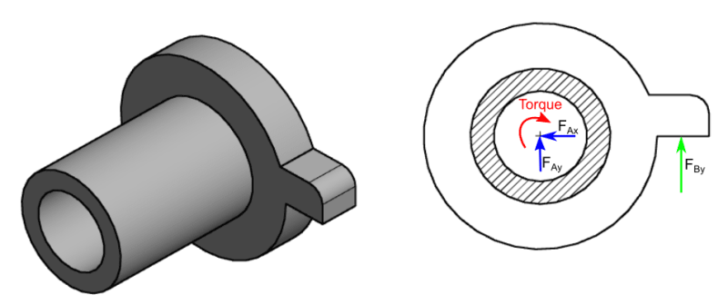
I use Abaqus Explicit for the simulation. The problem is that the reaction force at bearing B (F_By) is much higher than it should be judging from an experiment. When I add a spring (Abaqus: *SPRINGA) between bearing B and the part, the reaction force there (F_By) completely changes and is closer to the experiment. If I only use bearing A with a complete fixation (encastre) the reaction moment is correct. Why is the reaction force at bearing B overestimated and how can this problem be solved?
Thank you in advance for your suggestions!
P.S.: For the boundary conditions I use for each bearing a reference point that is coupled to the surface where the bearing and the part touch each other. The geometries of the bearings themselves are not modeled. I use C3D8R elements.
I'm trying to get the correct bearing reaction forces from the simulation of a torque rod. There are two bearings. Bearing A fixes the part on the rotation axis but allows for rotation (roller bearing). Bearing B inhibits the roation (basically a connection to the ground). The torque is applied on the other end of the rod and occurs within a short time period. The setup is displayed in the attacched image.
I use Abaqus Explicit for the simulation. The problem is that the reaction force at bearing B (F_By) is much higher than it should be judging from an experiment. When I add a spring (Abaqus: *SPRINGA) between bearing B and the part, the reaction force there (F_By) completely changes and is closer to the experiment. If I only use bearing A with a complete fixation (encastre) the reaction moment is correct. Why is the reaction force at bearing B overestimated and how can this problem be solved?
Thank you in advance for your suggestions!
P.S.: For the boundary conditions I use for each bearing a reference point that is coupled to the surface where the bearing and the part touch each other. The geometries of the bearings themselves are not modeled. I use C3D8R elements.