Continue to Site

Eng-Tips is the largest engineering community on the Internet

Intelligent Work Forums for Engineering Professionals

  • Congratulations KootK on being selected by the Eng-Tips community for having the most helpful posts in the forums last week. Way to Go!

Boundary Conditions for Axle

Status
Not open for further replies.
Replies continue below

Recommended for you

I'm not sure I understand what you're asking !?

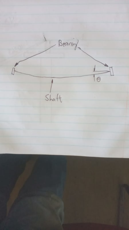
Your sketch shows the situation well. We'd say that the beam is simply supported.

another day in paradise, or is paradise one day closer ?
 
It depends on how this axle is supposed to be supported in real life. Try to visualize how it’s mounted and which degrees of freedom are constrained by bearings. Usually, a standard simply-supported beam scheme is assumed.
 
Hi

It’s a simply supported beam in its simplest form however the sleeve over the shaft is it a loose fit or an interference fit?. If it’s the former then some of the bending will impinge on the shaft, but if it’s the latter the shaft will be a lot better at resisting bending.

“Do not worry about your problems with mathematics, I assure you mine are far greater.” Albert Einstein
 
I simulated supported beam.
I wasn't sure how to configure a simply supported beam in solidworks (I'm new to FEA).
I figured it out though.

Thanks for the input everyone.
 
I'm varying the round bar length inside the tube to see how it effects the simulated results.
In both instances shown in picture, the results were the same.
I expected the displacement and stress to be less in the bottom configuration (see picture)
 
 https://files.engineering.com/getfile.aspx?folder=4fdc5c93-c693-4c83-acc8-4555ca8f36a3&file=Capture.JPG
How are you modelling the two pieces ?

Are you using a simple beam element with different properties ?

Or have you meshed the two pieces with 3D (solid) elements ? Then how are you joining the interface surfaces ?

I'd've expected a small difference in displacement ... the I of the tube section is maybe 90% of the solid section (depending on geometry)

another day in paradise, or is paradise one day closer ?
 
The bending resistance depends on the diameter and area moment of inertia. You can compare diameter and inertias of both sections and see why results are like that.
 
rb1957
I modeled the two parts as one solid body.
I then treated the solid as a beam.

I tried another test.
I removed the solid bar and simulated the tube only. The displacement and stress didn't change

I then added the bar back and looked at the simulated model. As you can see from the picture, it looked like the simulation is ignoring the solid bar
 
 https://files.engineering.com/getfile.aspx?folder=f4eb4b01-07d3-418a-b43d-827220d92b26&file=Capture1.JPG
ok, you have two beams ...

1) solid, and
2) tube.

there should definitely be a difference in deflection.

how are you "treating the solid as a beam" ? are you modelling with beam elements or 3D solids ?

another day in paradise, or is paradise one day closer ?
 
rb1957

The steps I took are outlined in the picture.

To answer your question with my limited knowledge: "are you modelling with beam elements or 3D solids ?"
I modeled a solid body (the tube and bar is one solid body). I then treated the solid body as a beam.

I hope this answers your question.

 
 https://files.engineering.com/getfile.aspx?folder=93d637c8-9341-42b4-98a8-1189ff7d4ee7&file=steps.JPG
Hi Michael

There is something not right a tube versus a solid bar should have different stress and deflections, unless of course the tube and solid have the same mechanical properties and the same second moment of area’s which I very much doubt.

“Do not worry about your problems with mathematics, I assure you mine are far greater.” Albert Einstein
 
My new approach is to simulate as a solid body rather than beam. The ends will be fixed.

For a fixed beam on both ends
Max Moment = wL[sup]2[/sup]/12
Max Displ. = wL[sup]4[/sup]/(384EI)

For a simply supported beam
Max Moment = wL[sup]2[/sup]/8
Max Displ. = 5[wL[sup]4[/sup]/(384EI)]

With these formulas, I'll deduce the max stress and max displacement.


Weight is the easy part. Also loads due to osciullating CG of reel and start/stop torque.
 
we use different words.

what do you mean by "I then treated the solid body as a beam." ?
For me I first build the model geometry (like a solid bar), then FEA steps are ... mesh it, apply loads and constraints, and then analyze.

Are you using the FEA embedded in SW CAD or the SW FEA ?

What do you mean "My new approach is to simulate as a solid body rather than beam. The ends will be fixed."

another day in paradise, or is paradise one day closer ?
 
rb1957
what do you mean by "I then treated the solid body as a beam." ?
Look at picture, steps.JPG. The 2nd step I clicked "treat as beam"

Are you using the FEA embedded in SW CAD or the SW FEA ?
SW FEA

What do you mean "My new approach is to simulate as a solid body rather than beam. The ends will be fixed."
I'm using solid elements, not beam elements.
I did this because when I was using beam elements, the simulation was ignoring the solid round bar.
 
mea culpa.

I've never seen this "treat as a beam" before. This looks to be a very "dumbed down" (no slight intended) approach to FEA (not a fan).
I think you're using the FE solver embedded in SW CAD.

"I did this because when I was using beam elements, the simulation was ignoring the solid round bar."

ok, I think SW was not understanding your model. Rather than "fixing the ends" and changing the SS beam to a dbly cantilevered beam,

1) model a solid bar over the span, keep SS, and
2) hollow out the solid to make a tube (over the entire span). Then
3) fill some of the bore from both ends (and make a void in the middle), and protrude this to make the first sketch.


another day in paradise, or is paradise one day closer ?
 
the basic idea is that bearings are simple supports, but you have to ensure that certain things are in place for that to be true. An axle cannot be designed only for stress. Deflection is an important requirement. The amount of rotation that occurs at the supports is also important. If the amount of rotation of the shaft at the bearings is too much then the bearings will start to resist this rotation and you will end up with clamping stresses and a degree on fixity on the end supports. Shigley does give a guideline for this maximum amount of rotation at the end of the simply supported beam, but I don't recall what it is. if you have codes for this I suggest you consult them (assuming they have guidelines for this). I cannot really comment on the FEA aspect of this.

WhatsApp_Image_2022-03-03_at_11.26.06_AM_zdjmbi.jpg
 
Status
Not open for further replies.

Part and Inventory Search

Sponsor