Continue to Site

Eng-Tips is the largest engineering community on the Internet

Intelligent Work Forums for Engineering Professionals

  • Congratulations GregLocock on being selected by the Eng-Tips community for having the most helpful posts in the forums last week. Way to Go!

Boundary conditions setting error

Status
Not open for further replies.

Nir_k

Mechanical
Apr 13, 2021
40
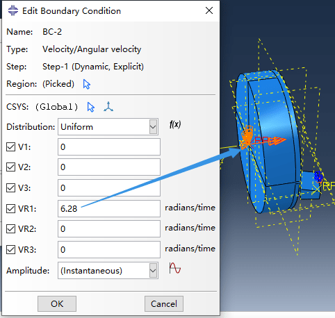
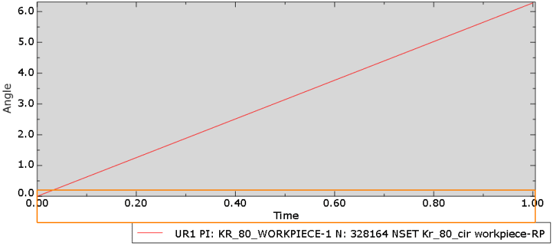
I tried to use Abaqus for external turning simulation, set the workpiece speed to 6.28/s, and set the analysis step time to 1. Theoretically, the workpiece should rotate one revolution, but the output shows that the workpiece reference point did rotate one revolution, but the rotation involved in cutting seems to be only a small rotation.
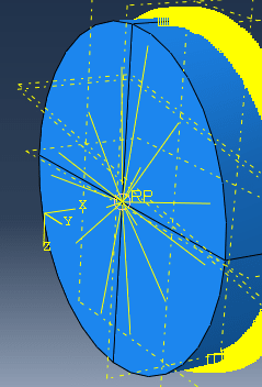
1. the f0llowing figure shows my boundary conditions set for the workpiece(The workpiece reference point is coupled to the left cross-section.).
boundary_condition_t67dhu.png

coupling_k8wjyx.png


2. And the following figure shows the rotation angle of the reference point on the workpiece.
output_qklnrg.png


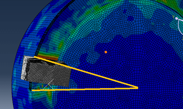
3. The cloud diagram below shows how little the workpiece actually turns.
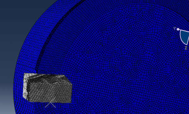
start_claay4.png

end_esmkuj.png

I would like to know why the actual rotation angle of the workpiece does not match what I set, and how I can set it so that they match. Thank you very much!
 
Replies continue below

Recommended for you

Did you check the deformed shape plot frame by frame and in form of an animation ? Are you sure that you are looking at the final deformed shape (at time step equal to 1) ?
 
Hi FEA way, thank you for your reply!
Yes, I carefully checked every frame of the animation and the result shows that the right cutting end is rotating very slowly, the final result at step time 1 is the legend with the yellow comment line above.
 
To make sure that it's not a technical issue, try restarting Abaqus and loading the .odb file again. Does the cutting work properly - are elements removed from the mesh once impacted by the tool ?

Can you share the .cae file ?
 
Hi FEA Way, thank you very much for your patience!
I just changed the angular velocity of the reference point to 31.4/s and the damage evolution value of the material from 0.001 to 0.1, but it seems that the actual rotation angle of the workpiece still doesn't match the setting (not 5 turns), or even smaller.
Sorry, my .cae file is too big to upload(over 20MB), here is the corresponding .inp file, looking forward to your answer again.
 
 https://files.engineering.com/getfile.aspx?folder=6d612e97-8a80-4b4c-9e84-c17b747450d0&file=Kr_80_cir.rar
Try further adjusting the damage criteria and (even more importantly) fixing the mesh of the workpiece right next to the initial position of the tool. Elements in that location are quite severely distorted and there are clearly problems with cutting the first layer of material during the simulation.
 
FEA way, my dear friend, appreciate you for your answer, I will modify the model according to your suggestion.
 
Status
Not open for further replies.

Part and Inventory Search

Sponsor