Continue to Site

Eng-Tips is the largest engineering community on the Internet

Intelligent Work Forums for Engineering Professionals

  • Congratulations KootK on being selected by the Eng-Tips community for having the most helpful posts in the forums last week. Way to Go!

Bracing top flange of a W36 in SAP2000

Status
Not open for further replies.

WayneRuin10

Structural
May 10, 2020
11
Hello All,

I have a question about how I can add horizontal bracing between 2-W 36 roof beams that are spanning parallel to each other. I have modeled this on sap2000, so i need to make sure when i add the bracing, they are attached to the top flange of the W36 and not the centroid of W36. See attached picture.

Any suggestion is appreciated.

Thanks
 
 https://files.engineering.com/getfile.aspx?folder=e5e23e90-20d7-4b0f-be47-1b15f5c64591&file=Capture.PNG
Replies continue below

Recommended for you

Sorry that was just a schmatic to get my point across.
 
Why do you need to make sure they only brace the top flange?
 
The bottom flange is in compression at or near the column.

BA
 
I'd start with the following:
I've tried SAP2000's steel design features a few times over the years and find the settings to be fairly mind-boggling, so be careful. Inspect the results closely to make sure it's doing what you want it to do. I'd start with a simple model of one beam, not a frame.

Also, as BAretired stated, the bottom flange is in compression in the indicated region.
 
BA - that was what I figured. You don't really need to model the top flange bracing for that though, it's just an input into member design.
 
Thank you all. The direction we are going is different than indicated. PLease see attachedI pic. How would i go about modeling the cross framing between 2 beams that are running parallel?
 
 https://files.engineering.com/getfile.aspx?folder=a0311145-a492-462d-a929-e33791f26bee&file=4f691e447ea8b1a0c13a167ac0bd0bb2762a9fcf.jpg
Model everything as 1D lines (beam elements) unless there is something else about the loading condition that would warrant a more detailed model. That bracing would brace the beam torsionally so I would consider it top and bottom flange braced at that location.
 
W beams were simulated with 1D element, X bracing between the beams can not be simulated in the fea model. You could specify beam lateral support distance equal to X brace spacing. And hand check brace angle strength and stiffness requirement per Aisc appendix 6.

You have to simulate beam with 3D element if the adjacent beam take different load (experience different deflection and introduce extra load on the bracings).

—————————————————————
Shu Jiang, SE (Nevada). PE(Michigan, South Dakota,Missouri,Oregon), PEng (Ontario)
 
I don't know what you mean by modeling the cross bracing. It is true that a cross brace as you have shown in the pic which you attached would brace both beams against torsion. That detail is often used when the beams are fairly close together, but in this case, they are separated by one whole bay. The concept can still work for the beam, but, if the beam requires bracing, perhaps the column does as well.

If you are using purlins on the roof and girts on the walls, diagonal braces or 'kickers' may be used from beam to purlin and from column to girt.

Have you considered using a pre-engineered building? They would normally feature tapered beams and columns, which are perhaps more economical than standard sections.

BA
 
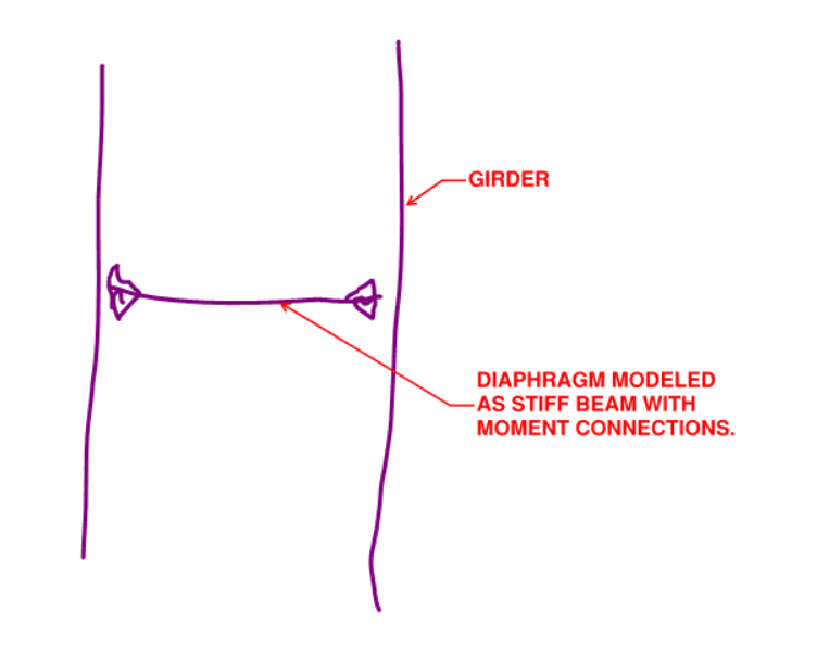
In the context of a line element analysis without eigenvalue buckling etc, the only modelling trick that I can think of is shown below. Basically, toss in a faux beam to represent your diaphragm element as best you can with respect to stiffness etc. That said, my normal expectation for something like this is a process like this:

1) Don't model the diaphragm.

2) Specify the unbraced lengths of your girders to reflect the influence of the diaphragms.

3) Design / detail the diaphragms using whatever procedure for the space that you're working in (bridge?).

If this is truly just two girders and diaphragms, also consider the potential for a twin girder buckling failure mode.

c01_pam6ea.png
 
Status
Not open for further replies.

Part and Inventory Search

Sponsor