Eng-Tips is the largest engineering community on the Internet

Intelligent Work Forums for Engineering Professionals

bracing working point 5

Status
Not open for further replies.

wrxsti

Structural
Sep 18, 2020
196
0
0
JM
if i design a bracing with working point at top of baseplate where no eccentricity to be considered

and then a 6" slab is poured covering 6" on top of baseplates

what effect does this have?

also in a redesign

could i consider this 6" above baseplate

a new working point without eccentricity consideration
 
Replies continue below

Recommended for you

Do you have access to the AISC steel construction manual? If so, check out the uniform force method special case #3 (page 13-9 in the 14th edition). It's similar to your situation but reversed - connected to the beam but not the column. Good example for how to balance the forces and moments. I know it's simple statics, but it's easy to lose that in the complexities of the brace connection design methods.

I'd post it, but I don't have it electronically and the onion-skin-style pages don't play nicely with my scanner.
 
phamENG yes i have considered special case 3 it however still works with working point at centroid intersection

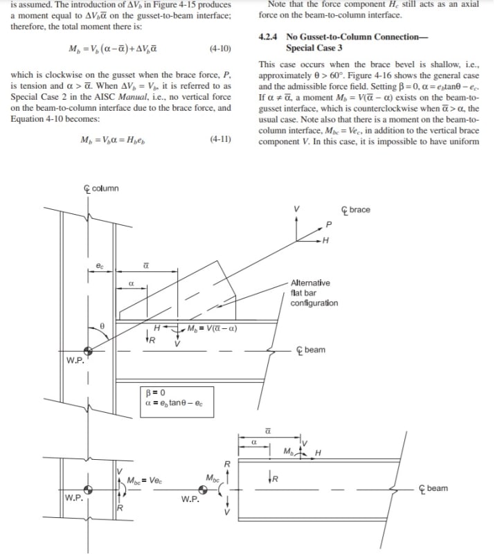
Untitled11_lgt8tm.jpg


for working point outside of centroid intersection

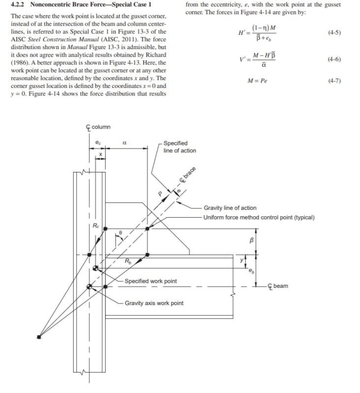
Untitled10_ieptmp.jpg


they talk about a moment P*e with e being the distance between the alpha - beta*tanteta = e[sub]b[/sub]*tanteta - e[sub]c[/sub] line (uniform distribution)
and the new brace line which in the example seems to be parallel

the new H' is developed from lets say for my case P*e/betabar


im guessing this Pe would relate to He + Ve[sub]c[/sub] ?? cant confirm this

in anyhoo

my situation has eccentric working point and zero baseplate connection

the admissible force field posted about with Fig. 4.22 includes Hb

im just wondering if could use the same force field and neglect Hb

and use the same H*e + V*e[sub]c[/sub] to develop H[sub]c[/sub]
 
No, I don't think you can. The case you posted up there resolves the moment at the plate to column interface with the horizontal reaction at the base plate. Since you don't have that connection, the statics will resolve themselves a little differently, and you'll have a moment at your gusset to column connection.

Remember, these formulas aren't hard and fast rules - they're just common cases that have had the statics pre-figured for you. Since you don't fit nicely into one of the boxes, you have to start from the beginning.
 
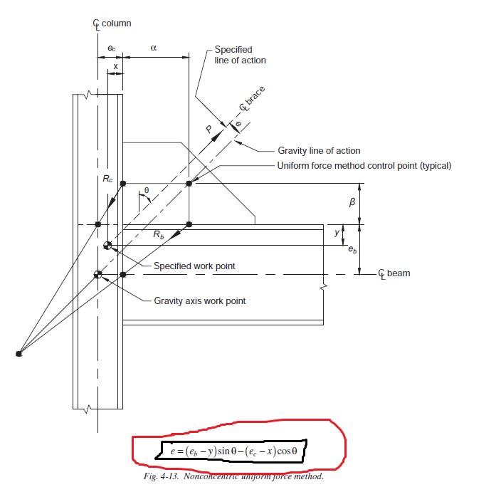
ok lets look at e

march9th_2_lds0gy.jpg


Pe = P(e[sub]b[/sub] - y)Sinθ - P(e[sub]c[/sub]-x)Cosθ

this turns out to be

Pe = H(e)


the column example is H(e) + Ve[sub]c[/sub]
 
@phamENG i see what you're saying i should consider H(β-e) - Ve[sub]c[/sub]

since there is no H[sub]b[/sub]β to resist it?

at the gusset column interface

so my tension yielding for gusset should be

Hc and H(β-e) - Ve[sub]c[/sub]
 
what i think i meant to say here is

if gusset centroid and gravity wp coincides F[sub]b[/sub]*betabar becomes F*beta+V*e ?
 
KootK said:
I don't know what to say... connection design is just difficult and annoyingly imprecise for deep thinkers. Sometimes I have to just throw the blinders up and fire up some software to keep things moving forward.

This thread and this sentence succinctly encompass exactly the kind of week I've been having...
 
Status
Not open for further replies.
Back
Top