Eng-Tips is the largest engineering community on the Internet

Intelligent Work Forums for Engineering Professionals

  • Congratulations waross on being selected by the Tek-Tips community for having the most helpful posts in the forums last week. Way to Go!

Bracket Design Help! 2

Status
Not open for further replies.

Will_s87

Mechanical
Jan 29, 2021
3
0
0
GB
Hi everyone, first time post & first time on the forum - (Im not a mech. eng.)

I need a bit of help with a bracket design....
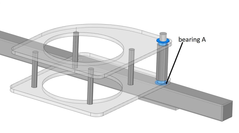
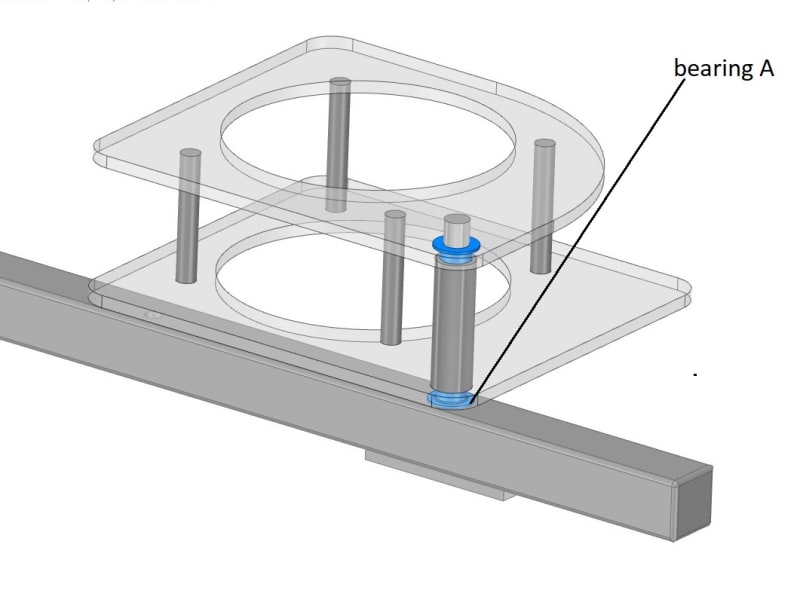
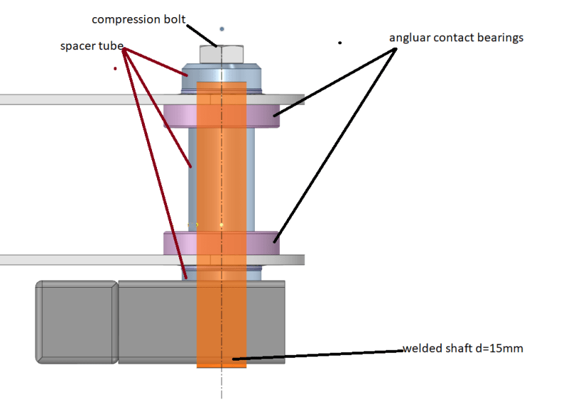
The images below show a bracket which will support a camera to inspect parts on a production machine. The bracket assembly needs to pivot about bearing A.
The total estimated weight of the bracket assembly is about 2.4kg .(uniform dist.)
The concern I have is that the bracket assembly will droop or tilt about the bearing A pivot point due to the weight and small support area of bearing A.
-Ive considered the following ;
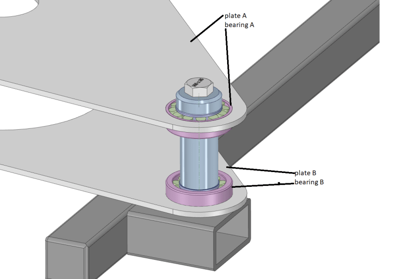
a) larger flange bearing to provide better support
b) tight tolerances to reduce any sag or slack in the hinge
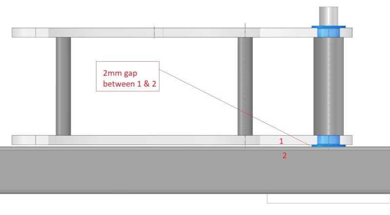
c) increase flange thickness on bearing A to increase the distance between parts 1 & 2 (image 3)

Could anyone offer any other ideas regarding the bearing and pivot point.
Its going in a food production environment and we cant use normal ball bearings

1)
pos1_jp0w2t.jpg

2)
pos2_orjhkk.jpg

3)
pos3_b6rwti.jpg


thanks
Will
 
Replies continue below

Recommended for you

Well, if your assembly sags, there are several possible reasons:
1. Play in the hinge. Use an appropriate fit between a shaft and a hole and/or have a larger area at the bearing.
2. Stiffness of the hinge shaft. Choose either thicker hinge or a stiffer material.
3. Stiffness of the structure as a whole. Adding triangles helps.
4. Stiffness of the individual parts of the structure. Use a stiffer material or increase thickness.

Or provide a support on the rectangular beam so the far end of the bracket slides on top of it. That way you don't care about the amount of sag under load.

Those are all the options as far as I see.
 
How much deflection ( angular and linear ) can your camera handle and still be expected to inspect the parts properly and reliably ?
 
As long as the bracket doesn't bottom out then wouldn't the deflection always be the same? Unless you changed to a different camera I guess. But if there are dynamics involved the camera may shake up and down through any backlash.

My experience with non-preloaded bearings in applications like this is that there will always be some slop. You might be able to get a tight fit in the beginning but repeated movement would probably create some looseness.

I'm guessing the bearings are plastic (for food handling)?
 
Do you need 360deg rotation? Can you have a brace that comes from the bottom bar to help anchor the top of the shaft?
I would do two things.
Make the bottom shaft mount permanent, welded. Don't use fasteners and risk them working loose.
Mage the shaft as large diameter as possible and make the lower bearing larger, as big as you have space.
Using the flanged bushings as bearings will work, but you will need to make them a little snug to minimize play.

= = = = = = = = = = = = = = = = = = = =
P.E. Metallurgy, consulting work welcomed
 
What are some of the dimensions? 2.4kgs is relatively light weight. I would expect more error from the shafting being not normal to the surface than error generated by the deflection from 2.4kgs. But without any dimensions that cannot be said for sure. Off eyeball-o-meter if the washer is 2mm then the shaft looks to be 12mm~. Is the deflection significant enough to matter?

Simple solutions; Add a nut on top of the shaft. Preloading the bearings should help. Ed is right though regarding the working loose of the nut. Consider a system to hold the nut (jam nuts, wires, tacking, etc.)

More complicated but still simple; Determine the bending the camera & mount system puts on the shaft. Add a counterweight to the opposite side.
 
You might be misunderstanding the bearing loading. As long as the camera mount assembly itself is relatively rigid then the loading on the bearings is simple, and all the load is transferred directly to the pivot shaft. The thrust bearing on the bottom sees no moment load, just pure linear force. You should consider lengthening the fixed shaft to go through the bottom of your square tube. This will give it stiff support. Then all the moment created by the load on the bracket is absorbed by the shaft as a bending moment. See the image.
 
 https://files.engineering.com/getfile.aspx?folder=6a0992ab-ae40-4763-82df-c44ffd4a7b12&file=frame_pivot.png
Hi Guys,

thanks so much for the replies, Thanks Jboggs for the diagram. The shaft is going to be welded in position so it cant come loose.
I've had to change the design slightly since my initial post. The pivot point has been movedand its been requested that I use angular roller bearings, the idea being that these can be preloaded and will eliminate any sag / wobble etc...


Here is what I've come up with so far..

image1 shows an over view of the new angular roller bearings.

image 1:
3d-view_pgtvbb.png


image 2 shows a side view of how I envision the compression / preload working.
The bolt shown at the top is screwed into the shaft (orange) and this compresses the inner races of the bearings down onto the box section through the "spacer tubes" -
image 2:
side-view_xvzscv.png


Question:
Without increasing the thickness of the plates to the same thickness of the bearings (10mm) to enable a press fit, are there any alternative ways of getting a good connection between plate and outer bearing race?

making top and bottom plates 10mm would allow the bearings to be press fit, it just seems a bit over kill to have a 10mm plate for a very small load...

thanks alot
Will
 
Angular contact bearings are a wonderful tool for high speed, high precision spindles. That is not what you have here. What you have here is basically a hinge, a reciprocating pivot. The type of bearing used here will have no impact on the amount of "sag" you might see. The sag isn't in the bearing. Its in the structure. If the structure is stiff, it will not sag whether you have any bearings there or not. Look at my diagram. If the axle is truly fixed, and if the structure is truly rigid, it will not sag.

How thick are your upper and lower plates?

How far is the center of the load from the central pivot centerline?

How much "sag" is acceptable? Do not say zero. That is unrealistic.

In your first post you said that ball bearings were unacceptable. Angular contact bearings are just a type of ball bearing. Why are they now acceptable?

Did someone suggest them because of their thrust load capabilities? If so, that is still a misapplication. Your thrust load is only 2.4kg. A simple bronze thrust washer will work for years.
 
Hi Jboggs -
thanks for your response - Ill do my best to answer your questions ; (I'm a machine programmer, not a mech eng, please bear that in mind [dazed])

1) "The sag isn't in the bearing. Its in the structure. If the structure is stiff, it will not sag whether you have any bearings there or not. Look at my diagram. If the axle is truly fixed, and if the structure is truly rigid, it will not gas."
By the structure do you mean
a) any components beyond the outer race of the bearing ?
b) any components beyond the fixed shaft?

- The reason for the change from journal bearings to angular contact bearings was the following;
using angular contact bearings would allow us to tighten or "preload the bearings (and pivoting assembly)" - this would reduce any slack between shaft and inner bear race...

- I think I agree with what you have said, but my worry is that during manufacture, if the fit tolerance between shaft and bearing ID, OR, rotating plates and bearing OD is not a tight fit, the rotating part will be wobbly.

2) - How thick are your upper and lower plates?
ideally 3mm, but i think if we go ahead with the bearings in the image the plate thickness will need to match the bearing thickness (10mm)

3) How much "sag" is acceptable? Do not say zero. That is unrealistic.
- 0.5 degree -

4) In your first post you said that ball bearings were unacceptable. Angular contact bearings are just a type of ball bearing. Why are they now acceptable?
to begin the pivot point was located directly above an empty can (that will be filled with food) - in that location only dry bearings were permitted - Ive been asked to relocate the pivot point so its beyond the limits of the empty cans

5) Did someone suggest them because of their thrust load capabilities? If so, that is still a misapplication. Your thrust load is only 2.4kg. A simple bronze thrust washer will work for years.
the idea was as follows
a) the rotating camera bracketry must have as little as possible sag (I know, I know) - and the easiest way to achieve this was to use a bearing that could be pre loaded and is capable of haivng radial and axial loads.
bear in mind its not an unreasonable idea that at some point operator may well lean on this ... turning the radial load from 2kg to maybe 40 kg?

thanks for your help


What material are the plates?
I have seen a dimple die used to flare the metal round the hole and create more contact in the Z direction.
It also tends to stiffen the plate.
These can then be reamed to fit bearings or the bearings can just be pushed in, depending on tolerances.

Part of what JBoggs was getting at is that roller element bearings do like slow limited movement.
You would be better off with journal bearings.With polymer bearings there are many ways to keep them snug.

= = = = = = = = = = = = = = = = = = = =
P.E. Metallurgy, consulting work welcomed
 
By "structure", I mean the rotating framework. The bearings are just a method of attaching a stiff framework to a stiff axle.

If you're concerned about the structure itself flexing under the load an operator might apply, then forget that it rotates and design it to support that load assuming fixed supports at the bearing locations.

The axle is basically a cantilever beam, fixed at one end (the lower bearing) and loaded at the other end (the upper bearing). Size it so that it will not deflect more than the acceptable amount by the moment created by the off-center load of an operator leaning on it.

I think in imperial units. It looks like your support frame consists of two 1/4" acrylic or aluminum plates separated by about 3". If I were doing it, my axle would be a piece of 1/2" diameter precision stainless rod. I would place a 1" OD bronze or plastic thrust washer around the bottom of the axle. I would press a 1/2" ID bronze or plastic flanged bushing in the bottom frame plate (flange down), and a plain 1/2" bronze or plastic bushing in the upper plate.

Slip the assembled frame with bearings over the axle and let it rest on the thrust bearing.

Go to lunch.
 
Compositepro's suggestion is the best one so far, and it appears it was overlooked.

You know what your 'payload' weighs. Counterbalance the assembly, and your concern about sag disappears entirely. Then use bronze bushings which cost a few cents, instead of bearings which cost a lot and need to be lubricated.
 
How much deflection ( angular and linear ) can your camera handle and still be expected to inspect the parts properly and reliably ?
 
Status
Not open for further replies.
Back
Top