Continue to Site

Eng-Tips is the largest engineering community on the Internet

Intelligent Work Forums for Engineering Professionals

  • Congratulations KootK on being selected by the Eng-Tips community for having the most helpful posts in the forums last week. Way to Go!

Brain warm-up requested. 2

Status
Not open for further replies.

itsmoked

Electrical
Feb 18, 2005
19,114
Hi! I have a customer with a mid-size machine shop with lots of different types of machine tools. About 2 years ago I was introduced to the place because a large CNC tool sporadically threw error codes occasionally when a tool-changer was operated. Turned out that a control transformer was tapped at a percentage point that on hot days (low PG&E voltage) was below a functional output. I up-tapped 3(!) taps to get the voltage centered on requirements and all has been well.

Until recently...

That same unit had it's $4k spindle drive motor toast.

Now there's a lathe that throws bizarre error codes out of a controller that stops the machine in its tracks. The guy finds another sub-unit on ebay, buys and installs it. It throws the same exact code! He calls the seller and the seller tells him the only time he ever sees that strange code is when the units are installed into an OPEN-WYE OPEN-DELTA (please read what I mean not what I type) system that has issues. He went on to say he saw it at a place where it threw codes only on weekends because the neighboring business were not running. He suggested turning on every induction motor he has to see what happens. Doing this made a difference!

The customer also stated that a machine with a 7-1/2hp motor is fed by a conduit that runs thru his office. In the last year he's realized he can hear that conduit buzzing a little when the motor is running and it has slowly gotten louder and louder.

Most machines have buck transformers to get the ODelta 240Vac down to 208V (Japanese machinery).

Yesterday PG&E showed up and installed a power monitor ahead of his meter and have since told him, "There's something strange happening.".

We're awaiting their written report (later today??).

Any suggestions popping into your heads?
Antidotes?
Things to check?
Changes to make?
Watch-outs?


Keith Cress
kcress -
 
Replies continue below

Recommended for you

Unless your customer changed his load, it doesn't seem reasonable that he should pay for PG&E's mistake.
The recorder was set to three wire. If it were set properly to four wire and connected, you'd have the voltage to neutral information as well. Also, I suspect the recorder was installed at the shop's meter base where it would fail to get the full loading information on the transformers. Regardless, the voltage balance looks bad. We've managed to correct voltage balance on an open wye-open delta by changing the transformers. Perhaps PG&E would agree to share the cost of the inverter solution proposed above.
 
When talking fortune, is this in the millions of dollars, or a few hundred?
 
Hi Bill! No heaters, all big machine tools.
They connected their instrument between the pole and the weather head.
That would be looking at the total load.
One of the other customers may be responsible for some of the strange current results.
I am not onsite and am guessing, but....
If those are three phase on a three legged core, there may be a phantom delta affect adding to the backfeed to lower phases.
When talking fortune, is this in the millions of dollars, or a few hundred?
Another guess... $50,0000 to $100,000???

I don't suppose that PG&E are open to suggestion?
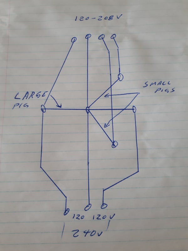
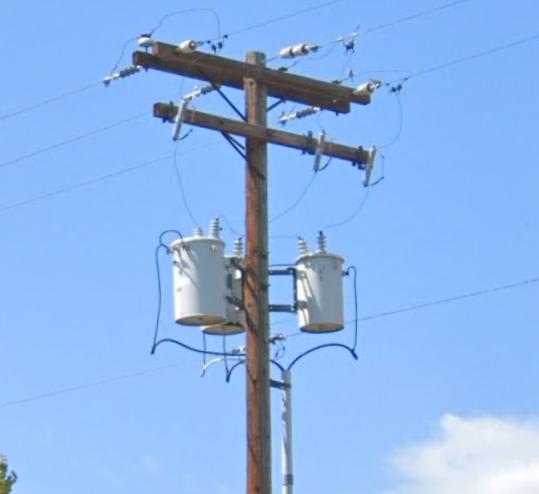
That teaser is holding the three phase load now. No need for a full blown wye setup with the majority of the load on the large transformer.
A second small teaser on the left side of the cross arm would supply 120-208 Volts as well as 120-240 Volts.
20200110_122857_1_hrneps.jpg

The metering is easily doable.
That may bring the cost down under $50,000
Guesses based on a pole and transformer installation about 10 years ago.
Estimate,- just a little better than a WAG. grin

Bill
--------------------
"Why not the best?"
Jimmy Carter
 
Good morning Gents. My qualification limit here is that my career through retirement was major utility switchboard design, somewhat pre computer.

I think that we've established that with VFD drives, delta motor contributions to voltage balance don't exist.

I would pass for the moment on the unbalance supply research because while unbalance could load up specific VFD rectifier poles, would their control system notice or care? I suspect that more likely they would just gate the 3 phases equally even if that exaggerates any current unbalance.

I note that as much as unbalance could be a continuing issue, the underground transformer fault last fall could have also seriously distorted the voltages & vectors until it cleared. If so has residual damage been left in the VFD or machine controls?

There is an ocean cruise passenger discussion board that is frequented by an active ship's chief engineer. He has mentioned that most cruise ships use 220v closed delta transformers with one side tapped mid winding as a neutral for 110v power. There is no solid ground, detectors provide the protection. This gives the ship European 220v delta for motors, lighting and cabin outlets for European passengers while providing 110v cabin outlets for the American passengers. His big point for us was that the cruise lines get upset at passengers bringing their own power bars because if they are surge protected to the ground pin the varistors or whatever can fry with the floating neutral and cause a fire.

Back to our machine shop, like the power bar makers, the VFD makers very likely assumed a neutral at a mid triangle, ground potential, in designing their surge protection. If so some of those 138.5v parts now have 208v on them. Aside from possibly being blown and ineffective, any random residual conduction could also jolt the logic negative bus enough to cause false signals.

So I would like to suggest that Bill Ross's Dec 24 post mentioning "Reality check" is the direction to look in. Try his voltage measure/vector sketch check and then try his symmetrical reference point transformer setup. It is the easiest, lowest cost idea to check and would resolve if a lack of a symmetrical reference point, at ground potential, is the problem. The only hard part will be determining if there is still damage in the various circuit boards from the underground transformer failure. A maybe check would be to move the synthetic reference wire from the suggested auxiliary transformers to the PG&E neutral/ground while some machines are running. If this direction proves out the next questions would be if the symmetrical reference point would remain at near zero volts through faults and if any chassis grounded surge protection could still be a problem. Take care not to become a ground source trying to act as a ground for PG&E's LV system nor a delta balancer for it.

I considered floating neutrals to be a protection problem and was surprised at PG&E's system. Around my area I only ever saw distribution with 1 transformer or 3, never 2. Small 3 phase users always had 1, plus 3 on the next pole, outside. So is PG&E's system frying surge protection in the VFD's and CNC controls? Is their standing offer of 240v open delta or 120/208v wye service at the customer's initial choice no longer suitable for today's customer equipment? Maybe this fell into an equidistant knowledge gap between them and their customers.

Bill
 
Welcome to Eng-Tips Bill West.
The PG&E report:
Keith said:
So PG&E came back with a power report finally. They connected their instrument between the pole and the weather head.
From the photos, the service drop from the weatherhead feeds a splitter that then feeds all customers.
As Steve pointed out, PG&E (Poor Grasp of the Equation?) used a three wire connection to meter a four wire circuit.
Seriously and truthfully, I once had an interaction with an engineer who was having serious issues counting to two.
The report tells us two things;
I There is something weird going on.
2 We need a better report.
Was this the same crew that disconnected the wrong building during the fire? grin
You have my sympathy.
I suggest that those current spikes and resulting voltage dips are being caused by another user with a large single phase load.
But I may be wrong. Look for a cycling load, either single or three phase.I hope that you are able to determine the source of those wild current balance swings.
Remember, the one graph is showing unbalance percentage, not actual current.
Another issue that may be considered:
The transformer fault may have caused damage to the system wiring that has gone undetected and unrepaired.
Bill W;
The two transformer solution is fairly common. I have seen it from The Yukon Territory to Honduras and points in between.
(I used to get out a lot.)
In a non industrial area served with 120-240 volt single phase power, it is a good solution to provide a small teaser transformer to drive a small three phase motor.
The motor and small transformer generally sort out between them any unbalance issues, often with no problems.


Bill
--------------------
"Why not the best?"
Jimmy Carter
 
I also welcome you B. West!

The two transformer 3Ø solution is what was used exclusively around here up until about 10 years ago when the three transformer wye (208) fashion came into it's own. Having driven back from WA via Oregon recently I was amazed to see that EVERY 3Ø service I saw in OR was now three transformers mounted 120° around the poles (probably to keep the phases properly balanced). I believe whoever supplies power in OR decided 'they shall all be Star'. Probably a power company that actually re-invests in it's infrastructure, something that, of course, doesn't exist in N.California.[cry]

Bill you're funny!! The burned place is in Salinas... The people, (engineers?), working on THIS job are not located here in Santa Cruz but are located in.....Salinas.
6faghec.gif


B.West. I've never seen a 20+ year old machine that had any protections depending on a neutral or even the ground. There are not even any screws available for a neutral. However, on new stuff, I definitely see a need for a neutral reference by the EMI stuff. A lot of new VFDs have warnings all over them saying you have to disconnect this or that screw if using non-wye power or you will void the warranty while simultaneously voiding any chance of not letting the smoke out.

I like Bill's scratchings of adding a third transformer but of course this is PG&E land and the mods have been "engineered and submitted to the city/county" for a permit so they aren't going to do anything more on the subject. I also think Bill's "a big transformer for the single phase loads and a second one to support small 3Ø loads" is turned on its ear at this site where the three phase loads probably exceed the rest of the single phase loads by more than 10 times.

After lots of pondering I expect the entire problem is simply too high a voltage being fed to all these machines owing to PG&E's poor voltage regulation and the machines all being 200V based.

The last time I repaired a machine in that shop it was a low voltage issue with a control transformer tapping out 90V instead of 110V. This was all before the vault transformer escapades after which I think PG&E upped the area primary voltage a bit.

BTW I was not able to go there Friday but must now go Monday.

Keith Cress
kcress -
 
Hi Keith.
Please take a close look at the "buck" transformers. I suspect a three phase, three core transformer with a floating wye point.
A floating wye point is a common mitigation of wye:delta issues, whether from a delta winding or from a phantom delta.
Talking to the owner today all his machining centers each have a "buck" transformer (he calls them). He described classic vertical E core configurations with coils on "each arm of the E". I'll lay eyes on them tomorrow.
This leaves me wondering. worth a close look.

Also try to find the source of that strange current trace.

Spitballing here in regards to the Transformer explosion:
BTW: These problems all started last fall when an underground vault transformer exploded about two businesses away. When power came back at this business a $4k drive was dead and machine misbehavior has now been the norm.
I wonder if a neutral connection was blown off at this time?
The multiple neutral grounding of the primary neutral could provide a bypass around a blown connection via the multiple grounding electrodes, but may introduce a resistance in the neutral conductor that is causing issues.

Bill
--------------------
"Why not the best?"
Jimmy Carter
 
Thanks for the welcome Bill R. & Keith C.
Bill R. -my exposure to 3 phase distribution is from years living in BC. Maybe BC also fits Keith's comments about Oregon spending the $ for wye secondaries.
Keith -thanks for accounting for the EMI protection aspect. Your comment about Oregon transformers being balanced is novel. I never thought of the weight distribution being an issue, although I have seen enough leaning poles that maybe I should have.

Bill
 
Hi Bill W.
I understand. I never saw an open delta until I moved away from BC.
The mounting brackets that Keith mentioned probably allow the mounting of larger transformers than would be prudent on cross arms.
The mounting brackets that i have seen are heavy galvanized steel.
Did you ever have anything to do with Kelly lake sub or Cathedral sub?

Bill
--------------------
"Why not the best?"
Jimmy Carter
 
I was actually joking about the balance. However! Very logically they appear to be trying to balance the weight distribution so it's not going to throw decades of lean into bending or twisting the poles. I think the slightly wider gap is so a lineman could actually maneuver thru them.

OR_xfrmr_fk728k.jpg


Keith Cress
kcress -
 
Right on all counts Keith.
A lineman with a short hot stick will have space to pull the cutouts.
I wouldn't want to put those three transformers on a single pole cross arm.

Bill
--------------------
"Why not the best?"
Jimmy Carter
 
I got by the place today. Sheesh. Probably 16 machine tools crammed into 3 bays.

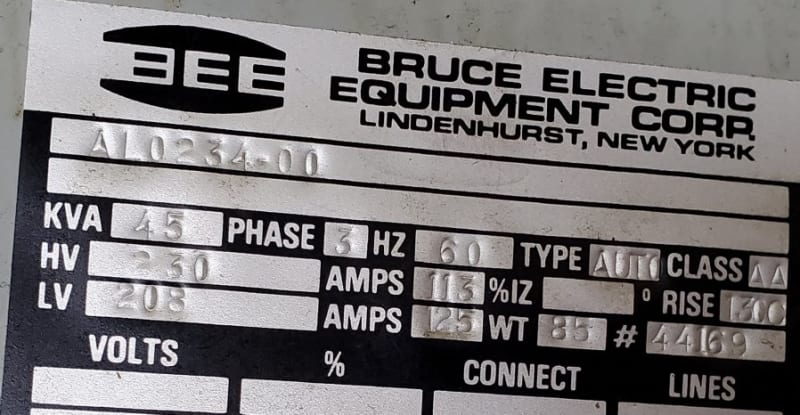
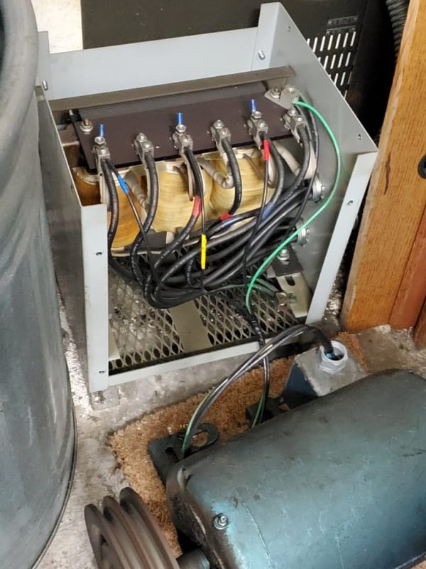
One a lathe with a 15hp spindle is bucked with this transformer. Clearly an auto transformer. Heck, it's 45kVA in about a 7kVA box! I've actually never seen one like this.

20200113_131833_nxfb9e.jpg


20200113_131706_laifaz.jpg


Note the running 5hp motor on the load side which actually improves the balance a couple of volts.

I measured the line coming into this transformer as a stake-in-the-ground 244V, 245V, 233V. Hows that for an imbalance! Gads.

I started looking in panels and discovered they're using the neutral bus for the ground bus with complete ignorance. Only one panel even has a ground bus and it and the neutral buses are both randomly loaded with grounds and neutrals and the bonding screw is installed.
47ipbn4.gif


Looking in only one panel their single phase is badly balanced 18A on one leg and 3A on the other.

I've prescribed:
1) Correct the grounding situation. Install ground buses and separate the grounds out from the neutrals.
2) Balance the single phase loads by making changes while watching the three phase voltages NOT the currents.

PG&E will be replacing the transformers Wednesday.

There is a possibly that one of the big lugs up in the air is crapping-out. They had that happen about 4 years ago and PG&E didn't even bother to re-do the other two..
316wvna.gif


Keith Cress
kcress -
 
The magic of multiplication and why I like auto-transformers to adjust the voltage.
A conventional transformer with 208 Volt and 22 Volt windings can be used in place of that auto-transformer.
With the 22 Volt winding rated for 113 Amps, that would be 4.3 KVA. (22 V x 113 A x 1.73 = 4300 VA)
Or with an open delta connection and two transformers at 2.5 KVA each. (22 V x 113 A = 2486 VA)
Note calculated for 208 V up to 230 Volts. The calculation is a little easier.


Bill
--------------------
"Why not the best?"
Jimmy Carter
 
Status
Not open for further replies.

Part and Inventory Search

Sponsor