Continue to Site

Eng-Tips is the largest engineering community on the Internet

Intelligent Work Forums for Engineering Professionals

  • Congratulations IDS on being selected by the Eng-Tips community for having the most helpful posts in the forums last week. Way to Go!

Breaking Torque

Status
Not open for further replies.

PeteSpear

Mechanical
Jun 19, 2020
5
A customer has asked me about calculating torque for brakes on a fly wheel to use in E-stop situation. They have no idea of the breaking torque required. At present the E-stop requires approx 5 seconds to stop machine while a controlled stop (using ramp down on motor drive) is around 2 - 3 seconds. Putting a shorter ramp down doesn't result in quicker stopping as the motor overhauls the drive.

I have suggested either a braked motor or DC injection but they are concerned the motor shaft would fail. I suspect this isn't a worry but anyway they would rather go with brakes on the flywheel. Soooo - can I calculate the torque produced to accelerate the line during start up (and thus calculate a reasonable approximation of the breaking force required to stop it) from a trace of the power pulled by the drive on start up?

When I say can I, what I mean is can any of you tell me what info you'd need to tell me the answer :)

Thanks

P
 
Replies continue below

Recommended for you

Oh, and yes, that should be 'Braking Torque@ ...
 
You can certainly establish the amount of torque used on start-up if you know enough about the motor's characteristics and the current demand on start-up. If it accelerates to start faster than it decelerates to stop, assuming it is some combination of an inertial and frictional load (not a gravity-overhauling load or anything of the sort), the stress on the components will be higher during start than during stop. "By how much" ... "what's the safety factor" ... requires an awful lot of information that we don't know.
 
As you say the power required to accelerate the line will be 'more' than that to stop it due to frictional losses. We also know he line stops considerably faster with product on it as it needs to do work to drive the product through. It would be possible to get an idea of the frictional losses by looking at the power required to keep the line turning (without product)with the difference between this and the power required to accelerate the line giving an idea of the inertia.

Having said that if I know the max torque required to start the line, and match the brake to this, it will have plenty in reserve as it will be assisted by, rather than fighting against, the frictional losses. It would of course be possible to add a further safety factor to this if required so that I know there is a minimum safety factor of 'x' plus the additional provided by friction.

Pete
 
With electrical braking, the motor cannot create more braking torque than it did accelerating torque, so breaking a shaft is not an issue if the motor is capable of accelerating the load safely. It also the follows that the simplest rule is that you cannot stop it any faster than you can start it. So how long does it take to accelerate the load, and how fast do they want to stop it? Start there, because if they want it to stop faster than it can accelerate, don’t bother wasting your time on any electronic braking method, go right to friction braking. But friction braking is where you can possibly break a shaft.

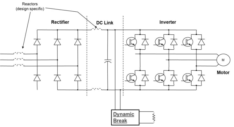
With a VFD (asduming that’s what you meant by “drive”), you have an added limit to stopping power if using Dynamic Braking Resistors, because the resistors and the chopper transistor firing into them have limitations, and those limitations vary by design so they must be discussed with the specific drive mfr you are using. But no matter what, your top end braking torque will likely be limited to 150% of motor rated torque at best (probably less), the difference will be in the amount of time the equipment can do that.

With DC Injection Braking, your motor becomes the biggest limiting factor. DCIB will transfer all of the kinetic energy of the moving mass into thermal energy in the motor, so as a gross general rule you must determine the Starts-per-Hour rating of the motor, then cut that in half if using DCIB, because each braking event becomes the same as a starting event on the motor from a heating standpoint. You also have to ensure there is sufficient time between starting and stopping events to allow the motor to cool, so that must be factored into the way the machine is operated.

If they do want full braking torque at 100% of motor Full Load Torque for an unlimited duration, you would need to change the VFD to a Line Regenerative Active Front End version. That way all of the kinetic energy is put back in the line (recaptured) for use by other equipment.


" We are all here on earth to help others; what on earth the others are here for I don't know." -- W. H. Auden
 
Thanks Jraef,

To answer a few questions, I believe the start up time is around 3 seconds but they want to stop 'instantly' (their words not mine). The line has relatively low speed rollers so 'instantly' could reasonably be interpreted as 0.1 second - at least this is what I will aim for and see where the figures lead. This is a lot faster than a typical start though not necessarily faster than it is possible to start. The line is pretty old and I suspect originally was either DOL or possibly star/delta but obviously no data exists for start times then.

I believe they have looked into adding braking resistors to the VFD (assuming this is variable frequency drive - I'm more used to hitting things with hammers than all this elastic trickery) and may even have tried it, if so without success. While I would enjoy the discussion and certainly learn loads looking into regenerative braking, their concern is only for an E-stop situation or total loss of power. I know there are ways around this with power supplies etc but it is their preference to use a mechanical brake. I only mentioned the motor shaft as they have said they don't want to use a braked motor (my first suggestion) so are looking at a brake on the flywheel. They call it a flywheel but it is actually a large pulley and I'm pretty sure its size is purely for mechanical advantage rather than any smoothing action given that the process is a rolling one without any kind of intermittent load.

Given that they have pretty much already decided they want a brake here, what they asked from me was if it was possible to calculate or even estimate the required braking torque. The obvious solution seemed to be to look at the info that is easily obtainable ie the motor rating plate and a trace of the current on start up. What I don't know how to do is convert this info into a figure I can use for specifying the brake.

Pete
 
If the pulley is 'flywheel sized' for the system then get good measurements of it and do the simple math, with the known motor speed, of calculating the energy stored in it. Do the same with any other inertia-looking aspects like the motor's rotor. Add them together and you'll have what a brake needs to supply.

It may be possible to use a disk caliper on the pulley itself excusing the motor shaft except for it's own inertia.

I think a more reasonable 1 second for stopping should be considered or you/they will be going in circles continually replacing everything that breaks. That will make the entire system considerably more dangerous because after a couple of E-Stop breaks operators will start to hesitate to hit the E-stops for fear of production loss or management second guessing/blaming.

What is this line they're trying to stop? Hope it's not a 70MPH Budwiser canning line.

Keith Cress
kcress -
 
For an E-stop to work reliably even in the event of loss of power, look at a spring applied brake, held off by air, hydraulics or magnetics.
Thrusters were used to brake the travel of gantry cranes.
They applied very fast but not quite instantly, to avoid breaking things.
Thruster


Bill
--------------------
"Why not the best?"
Jimmy Carter
 
When U frame motors were common, plugging to a stop was common.
With the current T frame motors, if you use plugging the T may stand for Toast.
I haven't seen a zero speed switch or a plugging switch for a couple of generations now.

Bill
--------------------
"Why not the best?"
Jimmy Carter
 
Hi Pete

I think the main formula you need is T= Ix alpha
Where I is the inertia of the flywheel etc

Alpha = angular acceleration

T = torque

The angular de-acceleration will depend on the time you wish to stop the system from rotating.
Calculate the energy stored in the flywheel etc at running speed and this will be the amount of energy you will need to dissipate in the time you wish to stop the system.


“Do not worry about your problems with mathematics, I assure you mine are far greater.” Albert Einstein
 
Don't forget the "etc".
I have seen systems where the "etc" inertia greatly exceeded the flywheel inertia.

Bill
--------------------
"Why not the best?"
Jimmy Carter
 
Thanks for the suggestions guys, I have at least 6 rollers all with unknown weight and unknown construction - they're almost certainly hollow but I have no way of knowing (even if I were to weigh them) how the weight is distributed so calculate their inertia. Hence the reason I am asking for an equation that allows me to calculate using what I do know (or can easily find out) using the electrical power input.
 
Hi Pete

Well you could start with just the flywheel but I think what you will find is that you won’t be able stop it in less than one second as indicated in earlier posts. I once worked out on stopping a flywheel in less than a second the power required to do this ran into MW after that calculation I did the braking was forgotten.

“Do not worry about your problems with mathematics, I assure you mine are far greater.” Albert Einstein
 
You can try something like this
Screenshot_from_2020-06-21_14-19-29_mynv5p.png

Spring-set, magnetically released emergency-duty caliper brakes (photo is from I purchased a crane with an emergency hoist break of a different design - Air release, spring to set. Stopping at full hoist speed was about 1/8 rotation using the proof test weight. As the drive train is not involved in the stopping torque in the crane application, over sizing the caliper brakes does not make too much trouble, but I did require builders calculations.

Your description could still be anything from a 6 roll straightening machine to a roller conveyor. The straightening rolls might have solid rollers. Almost all of the conveyor applications would use tube or pipe rollers. So depending on the rest of the drive train - is it some sort of gearbox, or chain and sprockets (and how much design margin is built in)the importance of knowing the details of how the torque of the proposed e-stop brake is distributed through the system varies quite a bit. The faster the equipment must be stopped the more important the calculations become as you are more likely to use up all of the design margin.

As a point of reference not even saw stop uses the term instant.
Their product is a single use brake that stops a table saw blade in 5 milliseconds (some of the videos show the saw stopping without injuring the test hotdog). It is costly to meet that sort of goal, as it requires an single use actuator, and stops production until the unit is repaired.
 
Oh, and yes, that should be 'Braking Torque' ...

Good self-correction.

Puts me in mind of the time a Commissioning Report came across my desk advising an "Air Brake Switch" had been installed...I guess that's what happens when you let a Transport & Work Equipment mechanic loose in a power distribution environment.

CR

"As iron sharpens iron, so one person sharpens another." [Proverbs 27:17, NIV]
 
How about the time when a secretary transcribed the expense account submission;
"The amounts of the prorated expenses were calculated with a Sly Drool."

Bill
--------------------
"Why not the best?"
Jimmy Carter
 
If you calculate the braking torque from the motor acceleration time it will be more than fast enough.

Bill
--------------------
"Why not the best?"
Jimmy Carter
 
Someone just sent me a PowerPoint presentation to use in training salespeople on VFDs (I make my own, but they thought they were helping). They are in Brazil, so ESL undoubtedly.
VFD_topology_umwakq.jpg


" We are all here on earth to help others; what on earth the others are here for I don't know." -- W. H. Auden
 
Status
Not open for further replies.

Part and Inventory Search

Sponsor