Continue to Site

Eng-Tips is the largest engineering community on the Internet

Intelligent Work Forums for Engineering Professionals

  • Congratulations SSS148 on being selected by the Eng-Tips community for having the most helpful posts in the forums last week. Way to Go!

Bridge beam design

Status
Not open for further replies.

BAGW

Structural
Jul 15, 2015
392
HI All,

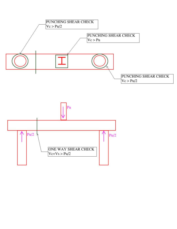
I am designing a bridge beam spanning between two piles which is 24" deep. The beam spans 5'-6" and factored load on the beam is 200 kips. I am checking the following,

1) Punching shear for the beam under the steel column
2) One way shear for the beam at a distance "d" away from column. Provide stirrups as plain concrete is not sufficient to resist one way shear.
3) Punching shear under the piles.
4) Torsion check assuming 3" offset for columns. As the beam is deep no torsional reinforcement is reqd.
5) Provide reinf for bending of beam btw piles.

Is there any other any other check that needs to be done. Is there any requirement at concentrated load location?

Document1_gamdyr.jpg
 
Replies continue below

Recommended for you

Rod,

These are old school thinking on pile-cap joint fixity.

Inkedjoint_LI_wasser.jpg
 
Design for the continuity that's ultimately going to be present, don't treat it as a pin, because it's impossible to achieve in practice in monolithic concrete. Depending on the relive stiffnesses and loads at play here it could be a large or a small moment.

Ignoring the fixity and providing no top steel because your assumed strutstrut and tie model said so is flawed. Your model isn't really correct in this sense, as it doesn't reflect what is actually going to occur with development of negative moment at the supports. Not withstanding this, you'll no doubt have some minimum steel requirements to satisfy for both the top and bottom reinforcement.

Stop turning the column reinforcing outwards. This is very poor detailing and not supported by a strut and tie model for anchorage of the diagonal joint strut. Most codes preclude this.
 
retired13 said:
I've designed pile head with pinned condition many times whenever lateral load is negligibly small, and project is not located in high seismic activity region.

How you design is up to you, as this design is up to BAGW. I'm just saying I would not model the this configuration, as I understand it, strictly as a pinned connection. I would either model it as a frame with rigid connections (but free to rotate and bend the piles) or envelope the design by modelling it as pinned for the bottom steel in the beam and then as fixed for the top steel in the beam and for design of the piles.

Rod Smith, P.E., The artist formerly known as HotRod10
 
BAGW said:
With strut tie method gives only bottom bars.

Only with the assumption of the pinned connection to the piles that you've shown. If you model it as a frame, which is what you actually have, the strut and tie model will look completely different.

Rod Smith, P.E., The artist formerly known as HotRod10
 
The fixity of the connection should depend on whether the deflection of simply supported beam is acceptable or not.

A pinned connection model assumes that the beam can rotate on top of the piles without bending the piles. In this case, that cannot happen unless the beam separates from the pile on one side, or the beam cracks on top. This is generally considered unacceptable for concrete design. Barring that, there will be negative moment in the beam, and moments and shears in the piles.

Rod Smith, P.E., The artist formerly known as HotRod10
 
Rod,

A few quotes FYI.

Transportation Research Board said:
Fixity at the top of the pile is difficult to attain with the structural details commonly used. A fixity of 50 percent is usually attainable and has the advantage of approximately equal positive and negative moments, thus making efficient structural use of uniform flexural members. If deflections must be minimized, then increasing fixity is a very efficient way of achieving stiffness. A

Pile Engineering said:
The type of connection between piles and pile caps affects the load carrying capacity of pile groups. The fixity of pile head into pile cap, instead of pinning into pile cap, enhances higher lateral stiffness of the pile groups. For instance, for the same deflections, a cap with fixed connected piles can sustain far more loads than that of pinned connected piles. To satisfy the criterion of fixed connection, the minimum embedded length of piles into pile caps should be at least two times the diameter of piles.

fix_pile_jwhmax.png
 
Rod,

Also note that:

1. Pile cap is cast after pile has hardened, without proper detail, it is difficult to classify the two elements are monolithic structure. When assume pinned condition, we ever went as far as to provide bond breaker between the interface.
2. The beam-column joint in the buildings are usually well confined to claim/attain the fixity, however, the upper corner in OP's case is not confined by another structure, maybe a few feet of soil, which obviously can't provide required restraint to develop moment capacity on top face of the beam. Thus the fixity must come from the pile, so the minimum requirement to attain fixity is to assure both the beam and the pile have the same moment capacity by design. The assurance comes with a price - more reinforcing and complicate connection detailing, a price sometimes too steep for gravity-centric applications with quantity.
3. The argument on fixity is better avoid by simply provide the amount of steel according to the maximum demand for both top and bottom of the beam. Then it won't fail either way. For small project, this the way I preferred.
 
BAGW,

Assume superposition is valid, you may try this,

Untitled_vwdswp.png
 
BAGW,

For your benefit, please review articles available on deep beam behaviors. For which the moment distribution along its depth is non-linear, while the shear is the most critical. It was addressed in commentary of the older ACI code regarding deep beam design, and the deep beam shall have both longitudinal and transverse facial reinforcement for the sake of shear concerns. In engineering sense, your beam is not that deep, but per guidance of clear span/depth ratio, it is classified as a deep beam. Also, for your application (single narrow beam on two piles), when the beam gets deeper, there is a potential for rotation about the longitudinal axis of the beam due to incidental eccentricity, pay attention to it too when detailing.
 
"...without proper detail, it is difficult to classify the two elements are monolithic structure."

Call it what you will, but if there's reinforcing crossing the joint that is a significant distance from the compression bearing edge, when the beam bends, a force couple (i.e. a moment) develops. This is true regardless of whether the concrete is cast monolithically or not, unless the reinforcing pulls out or breaks, either of which is generally unacceptable.

The magnitude of the moment may be small, if the deflection is small and/or the columns/piles have a low stiffness. However, a designer neglecting that moment and the associated deflection, without proving it is negligible, is risking damage to the structure.

Rod Smith, P.E., The artist formerly known as HotRod10
 
The argument on fixity is better avoid by simply provide the amount of steel according to the maximum demand for both top and bottom of the beam. Then it won't fail either way. For small project, this the way I preferred.

Yes, assuming fixity of the connection and providing negative moment capacity equal to the resulting moments is generally at least adequate. Usually, it's fairly conservative, but it's the simple solution.

If a frame analysis is not done, the pinned assumption should be used to design the positive moment reinforcing in the beam.

Connections are never fully fixed and rarely, if ever, truly pinned. The designer can take the simple and conservative approach of checking both extremes, or take a more rigorous route to get a closer approximation of the true behavior and the associated reactions.

Rod Smith, P.E., The artist formerly known as HotRod10
 
Rod,

Frame analysis may not be realistic, as the piles are surrounded by soil medium acting like a spring. Are you suggesting LPile?
 
Frame analysis may not be realistic, as the piles are surrounded by soil...

Without soil properties and a analysis program the depth to effective fixity of the piles would have to be assumed. Once the frame analysis is set up, it's typically not difficult to run it twice using the extremes for the effective column length (typically 5' below ground and bottom of the pile will suffice). Given the proportions shown in the OP's sketches, it looks as though for that particular case it will not make much of a difference, as the piles look to be much more flexible than the cap beam.

Are you suggesting LPile?

Or Allpile. If either are accessible, a couple of quick iterations should produce a fairly accurate model.

Again, the simplest approach is to assume pinned connections to calculate the positive moment reinforcement for the cap beam, and assume a fully fixed condition for negative moments on the cap beam, moment on the cap to pile connection, and moment in the column (it's the same design moment for all 3, btw).

A somewhat less conservative approach would be a frame analysis with an assumed depth to fixity that is fairly shallow. Even assuming fixity at the groundline would likely not change the outcome very much for the analysis at hand, compared to running it through Lpile or Allpile to get a more realistic effective depth to fixity.

Rod Smith, P.E., The artist formerly known as HotRod10
 
Rod,

Okay. You are right. At least we can agree on this "Connections are never fully fixed and rarely, if ever, truly pinned. The designer can take the simple and conservative approach of checking both extremes, or take a more rigorous route to get a closer approximation of the true behavior and the associated reactions."

I think the rigorous route is appropriate for larger size project with budget.
 
I think the rigorous route is appropriate for larger size project with budget.

For most projects there's a tradeoff between design effort and construction costs. For a small one-off design (which is what this appears to be), the simple, conservative approach is likely the most cost-effective (assuming the designer is getting paid based on the time spent).

Rod Smith, P.E., The artist formerly known as HotRod10
 
Status
Not open for further replies.

Part and Inventory Search

Sponsor