Possible issues from renovating the Morbi footbridge
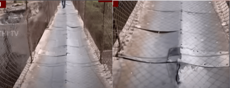
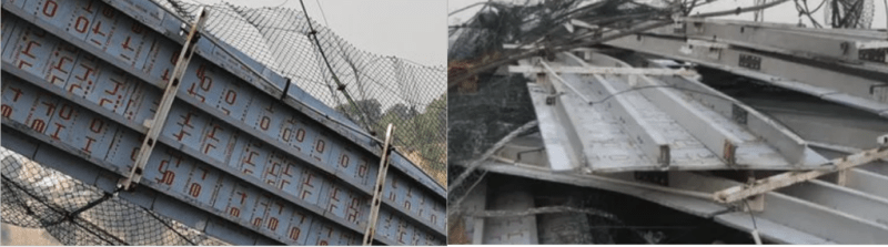
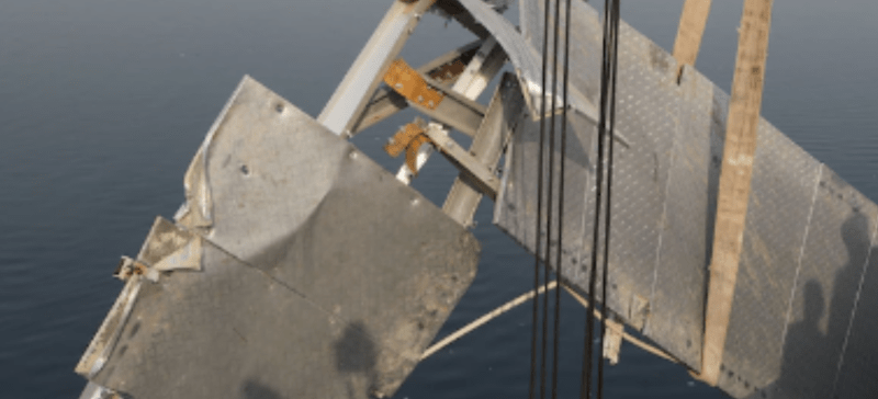
(1) New deck has 4 instead of 3 longitudinal beams in the old deck
From the old bridge before renovation the deflected deck clearly shows 3 longitudinal beams, one at each side plus one at the middle, to give the above symmetrical deflected dish shapes.
From the East tower hanging twisted deck and the debris the bridge deck after renovation has 4 longitudinal beams. This may cure the symmetric dish-shape deflection but the new deck's dead weight from the beam alone has increased by a factor of 1.33. The new deck surface also appears to be thicker possibly laminated with a hard wearing material.
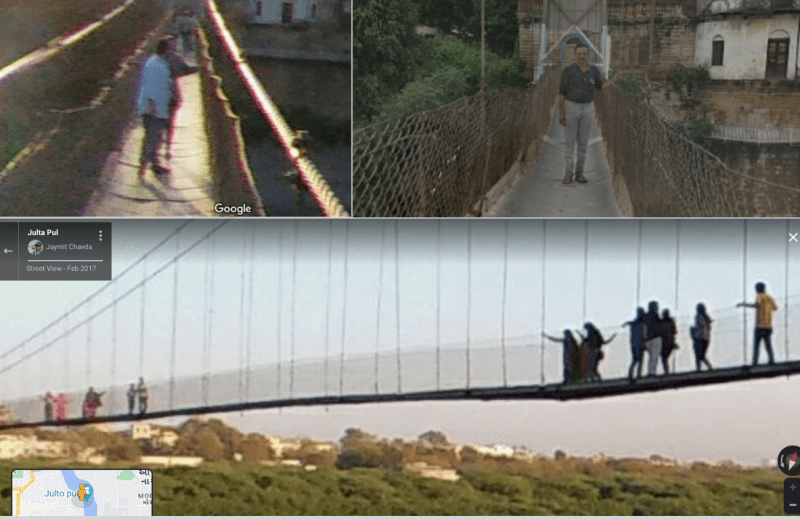
(2) The height of the chinalink fence, as safety barrier, has been extended.
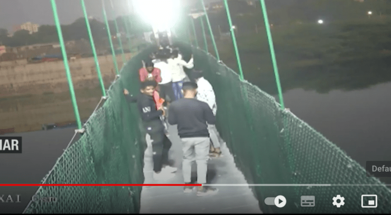
The old footbridge before renovation had a chainlink fence height which I estimate to be 1.2m to allow adults comfortably placing their hands on top of the fence.
The renovated footbridge has a new chainlink fence barrier clearly a lot higher than before as no pedestrian was seen taller than the fence. My estimate of the new height is that it is at least 2m as chainlink fence comes in standard sizes. The higher chainlink fence barrier is safer but the new height could increase the chainlink fence dead weight by a factor of 1.66.
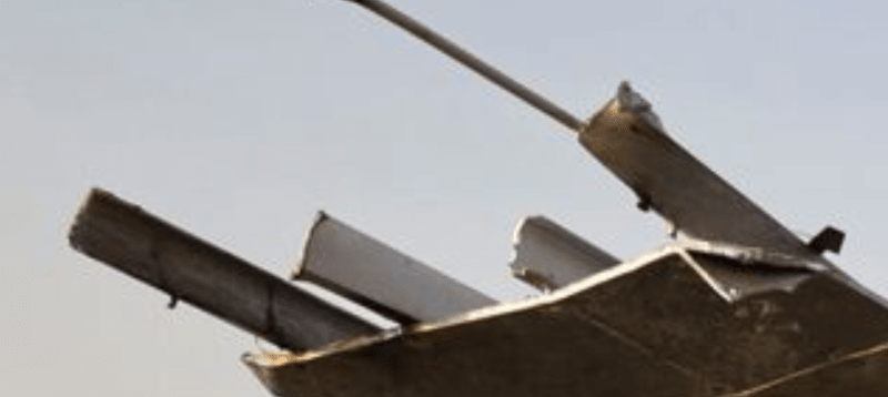
(3) Main cables were not replaced during renovation.
According to the preliminary investigation hearing the main cables were not replaced during renovation. The snapped off end has a fair amount of rust. Early evidence suggests the failure likely to have occurred at the top of the tower where each cable would pass over a pulley or saddle wheel which is used to balance out any unequal lateral force generated between the central and side span. Some Indian engineers have complained the cable should have been oiled or greased when passed over a saddle wheel. The lack of oil or grease could generate friction harmful to the cable.
It is not easy to snap off a steel cable with a universal safety factor of 5.
Observation
It is a miracle if the original design calculation of this 143 old bridge still exists. However even with an old general arrangement drawing and the limited foundation details a competent engineer can ascertain the capacity of each component by verifying its size, dimensions and material type. Thus selectively changing some components of the original design has to be back up by calculation that the capacity of the system has not been compromised. Extending the height and adding new beam will increase weight and that will have impact on the capacities of the deck, hangers, main cables, steel towers, connections, anchors and foundations.
The person who made decision on changes to the original design would have the knowledge that this bridge wobbles and vibrates. Thus the competency of the parties handling this renovation will be under a magnifying glass now.
![[ponder]](/data/assets/smilies/ponder.gif "[ponder] [ponder]")

 quite amusing, most comments are made by people that have never worked with a Whalla.
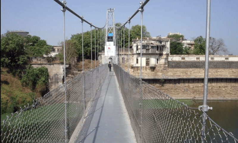

")