Greetings to everyone. First time posting!
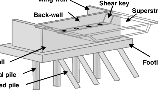
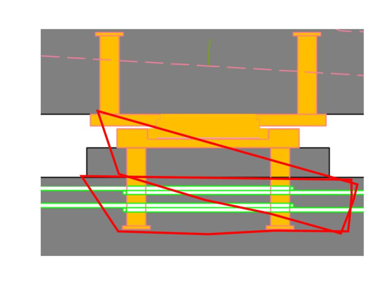
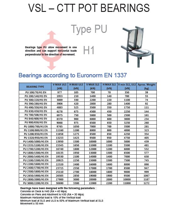
I have been asked to design an abutment and along with designing the reinforcement, check the connection of a fixed/guided bearing on the abutment. The aforementioned bearing has to be able to transfer 5000kN (1125kips) of shear force transverse to the bridge axis. I know bearings such as these exist and have found some approximate geometries (diameter, embedment depth, distance of anchors etc.), but looking at the pryout check I cannot seem to make it work.
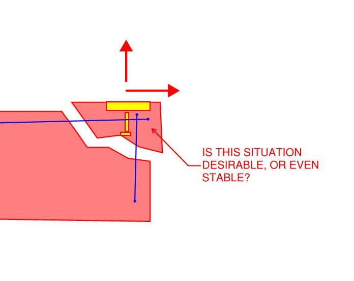
I feel that reinforcement should be the answer and having searched older eng-tip posts I know a lot of you agree, but neither the European nor the American Codes seem to allow for such a solution to my problem.
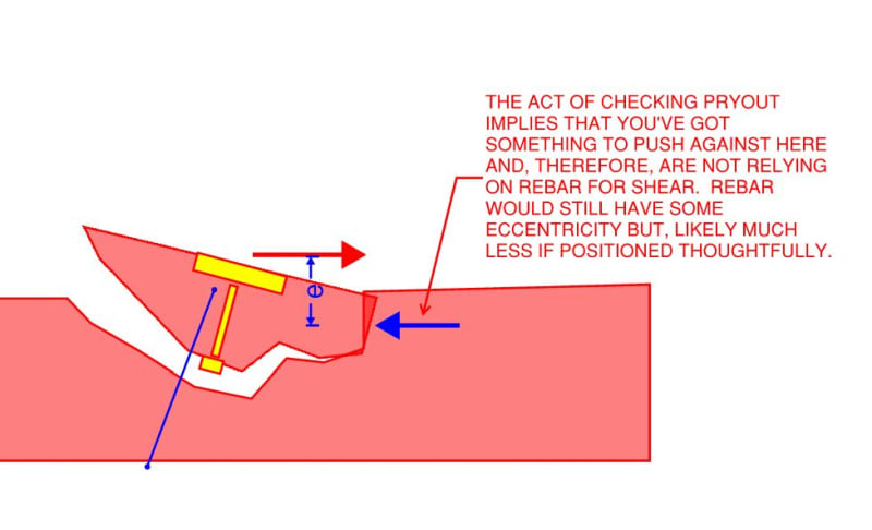
Having said all this and since bearings able to transfer this kind of (or even bigger) loading exist, I wonder what am I missing? Is pryout not an issue in such a case and if so, how would this be justified?
Thanks for any input!
I have been asked to design an abutment and along with designing the reinforcement, check the connection of a fixed/guided bearing on the abutment. The aforementioned bearing has to be able to transfer 5000kN (1125kips) of shear force transverse to the bridge axis. I know bearings such as these exist and have found some approximate geometries (diameter, embedment depth, distance of anchors etc.), but looking at the pryout check I cannot seem to make it work.
I feel that reinforcement should be the answer and having searched older eng-tip posts I know a lot of you agree, but neither the European nor the American Codes seem to allow for such a solution to my problem.
Having said all this and since bearings able to transfer this kind of (or even bigger) loading exist, I wonder what am I missing? Is pryout not an issue in such a case and if so, how would this be justified?
Thanks for any input!