Eng-Tips is the largest engineering community on the Internet

Intelligent Work Forums for Engineering Professionals

  • Congratulations waross on being selected by the Tek-Tips community for having the most helpful posts in the forums last week. Way to Go!

Bridge Parapet Distribution Among Girders as per Latest AASHTO?

Status
Not open for further replies.

Future_SE

Structural
Dec 5, 2018
8
0
0
US
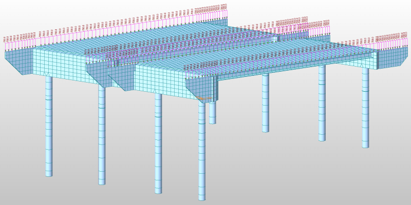
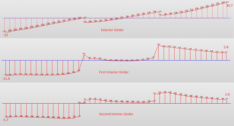
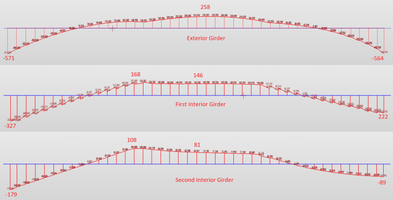
It seems that the distribution for dead load from bridge parapets is constantly changing in the AASHTO Specs. The latest edition (9th/2020) states "heavier concentrated line loads such as parapets, sidewalks, barriers or sound walls should not be distributed equally to the girders. Engineering judgement must be used in determining the distribution of these loads." This doesn't seem to give much guidance but I am currently designing a 120' span bridge with a 30 degree skew so I'm looking into how to distribute the parapet load among the exterior/interior girders. Does anyone have any suggestions on how to distribute these loads?
 
Replies continue below

Recommended for you

For large concentrated loads on the cantilever, such as a parapet, and for unbalanced loads, we used a transverse continuous beam (TCB) for the distribution. For bridges with sidewalks on both sides or curbs on both sides, we have typically used a uniform distribution to all girders. Occasionally, with a wide cantilever and raised sidewalks, we would use the TCB distribution for that as well.

In the past, interior girder typically had the critical loading, so it was conservative to use a uniform distribution. However, with the newer LRFD specs considering the superstructure rotating as a rigid body, that's not as often the case, anymore.

If the exterior girder controls the design, the TCB is the more conservative approach. TCB, is theoretically the more accurate way to distribute the load, but the difference in loading between the 2 methods for our typical curb and steel railing is negligible.

For your concrete parapet, probably TCB would be the more accurate approach, and more conservative than uniform distribution if the exterior girder controls the design.

Rod Smith, P.E., The artist formerly known as HotRod10
 
The classical options have been:

1. Tributary area
2. Lever Rule (Transverse Simple Beam)
3. Lever Rule (Transverse Continuous Beam)
4. Uniformly Distributed to all Girders
5. FEA

I've always been surprised that AASHTO ever even allowed the uniformly distributed method from the start. Even for longer span girder bridges, the weight of the railing never distributes equally to all girders.

For a new bridge of that length, the method that I use to distribute the railing load to each girder line would be the following:

Exterior Girder: 100% of the railing load
First Interior Girder: 50% of the railing load
Each Interior Girder Thereafter: Uniformly Distributed (If 5 girders total, each would then take 1/5)

I actually have a FEA model for a 136ft long pretensioned girder bridge on a 29 degree skew that I can show you how the railing load distributes. Mind you, the girders are integral with the abutments so it may be slightly stiffer than yours...

Railing weighs 700 lbs/ft so total weight across the bridge would be 95.2 kips per railing line. Exterior Girder end reactions are 68 kips which is 71%.

Honouliuli_kasrni.png

Honoululi_Girder_Shear_oiz8r8.png

Honoululi_Girder_Moments_khzjvn.png
 
Thank you both for your replies. I will be designing the interior and exterior girders separately so I planned on conservatively place 100% of the load on the exterior girder (since there is only a 1.5' overhang) and 50% of the load onto the first interior girder which I now know will have to be confirmed through analysis (most likely by a TCB analysis). Thanks again for both of your replies!
 
The TCB distribution would give you a slight uplift at the first interior girder. I believe the most conservative reasonable loading case for the 1st interior girder is the uniformly distributed load. For some configurations, slightly exceeding loading of uniform distribution at the 2nd interior girder with a TCB, is possible, but unlikely with a short cantilever.

TCB would give you a slightly higher load at the exterior girder (more than 100%), but with the short cantilever, it would be a minor difference.

Rod Smith, P.E., The artist formerly known as HotRod10
 
A bit of clarification.

The OP is referencing the commentary (C4.6.1.2.4b) about horizontally curved steel I-Girder bridges in Section 4 of the 9th Edition of the AASHTO Bridge Design Specs. This sentence remains unchanged since at least the 5th Edition in 2010.

Section 4.6.2.2.1 of the code states "Where bridges meet the conditions specified herein, permanent loads of and on the deck may be distributed uniformly among the beams and/or stringers." That sentence has also remained unchanged since at least the 5th Edition.

I couldn't find anything in the office that is older than the 5th Edition.

 
Thanks, OSUCivlEng. I suppose it makes sense that if the live load distribution is based on the assumption of a rigid cross-section, the dead load could be, too.

Athough it seems like a semantics thing, the AASHTO spec is fairly specific about where it uses "may" vs. "shall". In this case the user "may" distribute them uniformly, but may also use a different distribution.

There's also several "conditions specified herein" that theoretically would need to be verified in order to uniformly distribute the loads.

Rod Smith, P.E., The artist formerly known as HotRod10
 
I have a very experienced coworker who is very careful to differentiate between the commentary and the specifications. He often says the commentary is not the specs.

C1.1 of the commentary states:

The term "shall" denotes a requirement for compliance with these Specifications.

The term "should" indicates a strong preference for a given criterion.

The term "may" indicates a criterion that is usable, but other local and suitably documented, verified, and approved criteria may also be used in a manner consistent with the LRFD approach to bridge design.
 
Status
Not open for further replies.
Back
Top