Eng-Tips is the largest engineering community on the Internet

Intelligent Work Forums for Engineering Professionals

Bridge pier footing with sheet piling 8

Status
Not open for further replies.

Panars

Geotechnical
Apr 18, 2005
298
0
0
US
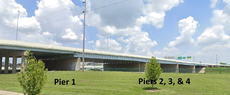
For the second time in my career, I have run across an existing bridge pier foundation that consists of a concrete footing with sheet piling around the perimeter. It looks like a normal pile supported pier footing, except there are no piles (like H-piles or pipe piles) under the footing, just the sheet piles around the perimeter. The sheet piles are driven in a rectangle and then the concrete footing is poured inside the sheet piles. The footing is a normal thickness (like 3 to 5 ft, 1 to 1.5 m) and is at the top of the sheet pile.

Does anyone have an idea how they designed these foundations? Are they designed as spread footings with an effective depth 2/3 the depth of the sheet piling (similar to a pile group)?
I don't think the sheet piling could be taking any significant load because the connection between the sheet piling and the concrete footing is relatively small. The connection is probably enough to provide lateral restraint to the top of the sheet piling, but that is it.

 
Replies continue below

Recommended for you

Looking at the detail title block on the drawing, it was designed and initialed under a title block for the City of
Dayton, OH, not the state DOT. Confirms what I recall of statements by Keyser, not something the state would do..
 
Plan Sheet 41A for Pier #1 has a note (in lower right corner) that says "For stem & cap details see Sheet 41." I take that to mean that Pier #1 still has, but Sheet 41A does not show, the HP14x73 bearing piles. Therefore, the SSP is not supporting axial loads from the pier.

 
The stem & cap detail note on sheet 41-A refers to section A-A on sheet 41 which shows a "temporary conc. cap" that is located at the top of each of the four piers. Next to section A-A is a "temporary conc. cap detail". Not referring to the pile cap.

In the 1950's it was common practice to have separate, stand-alone contracts for for both bridge substructure and bridge superstructure. The temporary cap was to protect the top of the piers from damage until the superstructure contract was bid / awarded. This bridge has a sizable structural steel supported superstructure. Structural steel shortages during and just after the Korean War (1950 - 1953) could have easily made it uncertain when the structural steel would be available... hence the need to protect the top of piers.

Dayton_Bridge-800_ax73n1.jpg


During and after US involvement in World War II (1941- 1945), some bridge construction projects that were underway were suspended for years until structural steel became available.

[idea]
 
Thanks, PEinc. Looking at the plans closely, I'll wager the original design was for all piers to be pile supported but with SSP around Pier 1 (located in Miami River flood plain) for potential erosion control. The Engineer must have noticed that with the SSP containing the soil, the pile could be deleted for Pier 1 (in a somewhat misguided cost control measure, as noted by both you and OG).

This would explain why Pier 1 is sized in both plan and elevation exactly like the other 3 piers.

From my time in Dayton, I know the consequences of the 1913 flood were a big deal and were taken seriously. There are large flood control dams and similar projects all over the Miami Valley... and 1953 was within living memory of that flood.

[idea]
 
The old SP-4 (or PSA28) SSP from Bethlehem Steel had a section modulus of 2.4 to 2.5 in.[sup]3[/sup]/LF of wall. I would be surprised if the SP-4 was capable of supporting the combined axial and bending stresses from 2.45 tsf [= (72 piles x 60 tons)/(110'L x 16'W)] footing load plus lateral active earth pressure when scour occurs (unless scour is very minor). This doesn't even consider settlement of the pier when the sheeting bulges out due to bending/deflection.

 
Great discussion everyone.
The plans were first prepared in March of 1953, but the Pier 1 revision is dated October 1953. So the sheet piling was a change. All the pier footings are at the same elevation, but Pier 1 is the only one that is out of the water. It would make no sense that I can think of for the pier on land to have added sheet pile by revision if it also had H-piles under the footing. So I agree with SRE that the H-piles were probably removed from Pier 1.

In my experience driving H-piles in the river in Dayton, it can be some hard driving conditions with cobbles and boulders. We have had the best results using 16-inch pipe piles with 1/2 inch walls and conical points. Maybe they had enough problems with driving the H-piles that they decided it wasn't worth it on the pier that was on land.
 
"Maybe they had enough problems with driving the H-piles that they decided it wasn't worth it on the pier that was on land."
So why would they think that it would be any easier to drive thin, narrow SSP instead of H-Piles? The SSP at Pier 1 does not look to me like bearing piles but does look like scour protection. If so, why would they worry about scour for a land pier but not the river piers? I guess they didn't worry about losing soil from around the bearing piles of the river piers. Strange.

 
Looking at the photo, maybe one pier is a "land pier", but this site likely can get high flood waters and then it no longer is a "land pier". Only slightly safer than "water piers" as to risks in the future.
 
I agree. But that does not explain why Pier 1 may have no bearing piles or how the SSP will prevent Pier 1 from, at least, settling or, at worst, even failing from scour. Maybe the SSP was designed to retain the soil under the pier when scour occurs while at the same time supporting the surcharge from the pier footing that does not have bearing piles. We can't check this without knowing the depth of scour below the pier foundation, the SSP length and yield Stress, soil properties, and if the Pier 1 foundation has bearing piles. I don't think the plans are very clear as to whether or not there are piles under Pier 1.

 
No way to know those sheet piles are the length shown on the plan. Could be sufficient hard stuff there that it is a good footing even in heavy flood times with short sheet piles, not meting plan lengths.. Has done so far as OK. Again, not a state DOT job, so who known.
 
I can't get a preview of those pages so excuse me if this is already stated in the book. I don't know enough about integral bridges but I remember someone telling me an integral abutment has to take relatively more lateral force than traditional bridges. Does that mean you want a pretty stout abutment that doesn't move at all or is a flexible foundation preferred? And in this case, why did they opt for sheetpiles instead of steel H-piles at the abutment location? I would think the connections for H-piles would be better suited for the lateral loads than the sheetpiles.
 
For some reason I cant see page 4 and 5 now either. It only had a paragraph or two on this bridge. I think it mentioned that this bridge was one of the first multi span bridges that didnt use rivets to connect girders.

I'm not an expert, but i think the general concept is you have a flexible substructure with a rigid superstructure that acts as a giant strut. The ones around here typically have piles with their weak axis in line with the bridge deck.
 
No problem, this is a serious subject. I had a first-hand experience with copyright infringement about 12 years ago (I was the guilty party who posted 1930's, but currently copyrighted material on my website.) Out of the blue, received an authoritative email from the copyright owner (a well-known and respected concrete industry association). To make a long story short, I literally called them the same day, admitted my guilt, removed the links on my website, and deleted the copyrighted material from my website's server. Fortunately we parted company on very good terms, without repercussions.

Made it a point to get as good a working knowledge of (US) copyright law as possible. Maintain a FAQ on the basics on the History Forum: Link.
Plan to update the FAQ, on or about 1 Jan 2020, everything printed and copyrighted in 1924 (that has not already) enters the public domain on that date.

[idea]
 
Status
Not open for further replies.
Back
Top