Continue to Site

Eng-Tips is the largest engineering community on the Internet

Intelligent Work Forums for Engineering Professionals

  • Congratulations IDS on being selected by the Eng-Tips community for having the most helpful posts in the forums last week. Way to Go!

Buckling Eigenvalue's with preload steps

Status
Not open for further replies.

Jbaden

Automotive
Apr 4, 2012
10
Hello All,

I am trying to determine the Buckling load in a mulit-body assembly, with preloaded fasteners.

I have the following steps
1. Initial
2. Preload step (with contact)
3. Preload 'Fixed' Step
4. Static, Perturbation
5. Buckle.

I have 150+ fasteners with preload (Summation of all preloads = 117 888 lbs).

In my Buckle step I have a Gravity load of 6179.2 in/sec^2 applied to the model weighing 2.182 lbf-sec^2/in. (Total Buckle Load= 13544 lb).

As per the .dat file Abaqus outlines the Buckling Load Estimate as follows:

----------------------------------------------------------------------------------------------
E I G E N V A L U E O U T P U T

BUCKLING LOAD ESTIMATE = ("DEAD" LOADS) + EIGENVALUE * ("LIVE" LOADS).
"DEAD" LOADS = TOTAL LOAD BEFORE *BUCKLE STEP.
"LIVE" LOADS = INCREMENTAL LOAD IN *BUCKLE STEP

MODE NO EIGENVALUE

1 = 0.10085
2 = 0.13904
3 = -0.16368

THE ANALYSIS HAS BEEN COMPLETED
----------------------------------------------------------------------------------------------

So correct me if I'm wrong but I predict my Buckling Load Estimate as per below:
BLE = Dead Load + Eigenvalue * Live Loads
BLE = Preload + Lambda_1 * 'Buckle Load'
BLE = 117 888 + 0.10085*13 544
BLE = 117 888 + 1 366
BLE = 119 254 lb

This does not align with my hand calculation estimate for a simple shell, est. 6800 lb. On the other hand when I remove the preload my buckling value is quite low at 1 366 lb.

Am I deteminining the BLE correctly, particularly the 'Dead load' or taking the dat file to literally?

Cheers,
Jakob


Cheers,
Jakob
 
Replies continue below

Recommended for you

Based on your description, the way you perform this analysis and interpret its results seems correct. However I’m not sure about the correctness of the comparison to simple shell model. Could you explain how it was calculated ?
 
I'm basically completing a Axial load capacity calculation for a simple 'plate' column under compression,

Rectangular Section = 3.57 in Wide X 0.14in Thick.
Unbraced 'Column' Length = 3.5 in
Material = 7075-T651

This is not ideal, however after discussions with some of the other engineers in my office, it seems that to gain a ballpark figure this method should be alright. The local region is heavily machined, to reduce mass, so a 'easy' hand calc is out of the question.

I also ran a static run, to determine the static stresses in the region. RF's produced in the order of +2.5, so it seems that somewhere my results does not make sense.

Thoughts?
 
Can you say more about the model ? What kind of structure is it ? And how is it constrained ? You described the loads but what's also very important is proper application of boundary conditions.

You could also try nonlinear buckling (so called postbuckling) analysis. This should give you much more accurate results than linear (eigenvalue) buckling procedure since the latter can be very misleading in some cases. But first make sure that there are no modeling errors.
 
Fastener preloads are not “dead loads” and should not be used in the buckling load calc.
 
SWComposites - Thanks! I did some experimental studies of a simple lap joint to determine the buckling loads, and came to the same conclusion. I've found that "Live" Loads can include 'Inertia loads' (when gravity is applied), model mass etc. Scanning the Abaqus documentation for Buckling, loads and keywords, there is very little if nothing about what contributes to 'live' and 'dead' loads. Any suggestion on where to look? Do you know if there is a summary in the *.dat or *.msg file of the summary of 'live' loads, I can't see any. I guess what I am looking for is something similar NASTRAN's OLOAD RESULTANT?

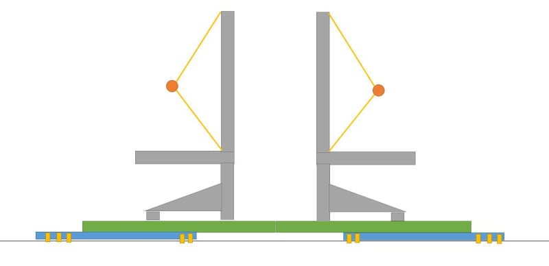
FEA way - I would love to post the model but unfortunately our company policy are quite restrictive on it. Essentially its a interfacing structure for a pair of seats, which secures into a helicopter floor. The interfacing structure consist of heavily machine Ally plate, with 'pockets' etc. It has multiple interfacing brackets, seat rails and a lot of fasteners (as you can guess).
- I'm using simple beam elements and couplings to transfer load between the parts, with preload applied in the middle of the beam.
- The model contains Surface-to-Surface contact between bodies.
- Boundary conditions are fasteners into the aircraft floor (the floor is not modelled), however in the image below it would be the yellow items. The Beam element is restrained in all 6 DOF at the shear plane of the model and the 'floor'.
- My 'Occupants' are modelled as Point Mass Elements, and is secured into the seat using Distributive Coupling elements as shown (representing the harness).

Currently my low buckling values are occurring in the green structures (two of them and not quite symmetrical), which is expected but the low eigenvalues are concerning.

SimpleSchematic_rftehh.jpg


Thanks,
Jakob.
 
FEA_way - I'm trying to stay away from non-linear buckling for as long as I can. As you can imagine, the complexity of the model will take days to run. However, you are right that non-linear buckling is probably the next best step to take.
 
you are not likely to find anything useful in the FEM documentation. it is up to you to understand and use "dead" and "live" loads; suggest looking at classical buckling texts. in this case I would ignore the whole "dead" loads thing and just consider all of your applied loads to be "live", to which the eigenvalue is applied.

but presumably you are sizing this structure for downward crash loads. with that and given the configuration I highly doubt you have a classical eigenvalue buckling case. rather you likely have a large displacement, high stress (beyond yield), etc case, which will likely require a nonlinear FE analysis for adequate analysis (nonlinear material and geometry - the whole ball of fun ....). and a lot of the energy absorption is going to come from fastener hole bearing deformation and fastener failure modes.
 
Hi All,

Just a quick update, after a few more reading sessions online and through the documentations I believe the following statements outline why my results for a Buckling Load Estimate using Eigenvalues were nonsensical.
- Eigenvalues are generally used to estimate critical buckling loads of stiff structures.
- Stiff Structures carry their loads primarily by axial or membrane actions, not in bending.
- Consider a classic Euler column under compression load.
- The column transfers its load axially not in bending.
- As bending occurs, the stiffness of the column changes dramatically.

So relating it back to my analysis above, our structure is primarily designed to transfer large bending loads. This in addition to model complexity through contact, load application, etc. explains why my results were nonsensical. After running a few balls down the steep RIKS (nonlinear FE analysis) hill, the results makes more sense.

Thanks all. Jakob.
 
Status
Not open for further replies.

Part and Inventory Search

Sponsor